4
Instructional Lea et IL03901003E
Effective May 2011
DS7 series soft start controllers, Frame 1 (4–12A)
EATON CORPORATION www.eaton.com
Control wiring
A minimum of 18 AWG should be used between the control power
source and the soft start controller terminals.
Terminal connections are to be secured to a torque value of
10.62 lb-in.
Control wiring is connected to the DS7 soft start controller on the
front of the unit. Use the wiring diagrams in Figure 3, Figure 4, and
the sizing/torque information in Table 9 as guides.
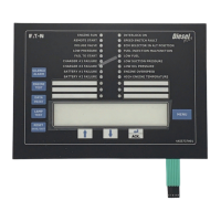
TOR
+A1–A2 13 14
24 Vac/Vdc, 110/230 Vac
+U
s
(+) U
s
(–) U
s
Q1
Direct start control wiring without soft stopFigure 3.
Direct start control wiring with soft stopFigure 4.
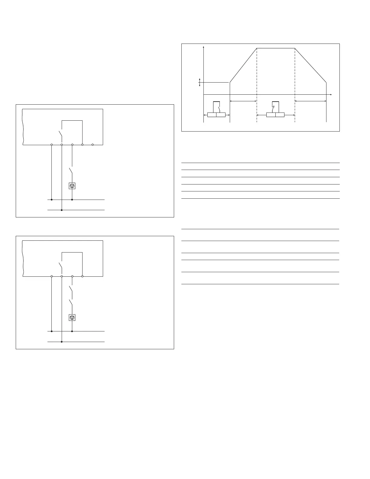
u-Start
U
t
13 –A2
TOR
(Top of Ramp)
t-Start t-Stop
13 –A2
TOR
Start and stop ramp functionsFigure 5.
Terminal designationsTable 8.
Terminal Description
–U
s
Control ground or circuit common
+U
s
Power of AC load
–A2 Common with –U
s
+A1 Run command
13 Top of ramp contacts—NO
DS7 terminal control block wiringTable 9.
Name
Block
Designation Input Connections
Circuit
common
–U
s
Common Control ground or
circuit common
Power +U
s
24 Vac/Vdc/120–230 Vac
maintained
Plus DC power or
AC load
–A2 –A2 Control power common Common with –U
s
+A1 +A1 24 Vac/Vdc/120–230 Vac
maintained
Run command
Relay 13 NO contact rated at 250 Vac,
3A resistive, 1A inductive
Top of ramp signal—
in bypass
Control power requirements
The AC control power for your DS7 soft start controller must meet or
exceed the following requirements:
Minimum supply current:
•
20 mA•
30 mA (with optional fan)•
100 mA (with optional fan, in bypass)•
Peak current requirement = 250 mA for 50 ms
•
TOR
+A1–A2 13
24 Vac/Vdc, 110/230 Vdc
+U
s
(+) U
s
(–) U
s
Q1
S3

 Loading...