I.B. 17555C
Effective November 1999
Page 10
High Load: The available high load time-out settings are
shown in Table 2.4. At a current 85% or above the inverse
time overcurrent phase setting value, the high load func-
tion will begin timing to the time setting selected and the
High Load LED will blink. If the current drops below the
85% value, the high load timer will reset, and only start
again when the 85% value is again reached. When the
High Load Timer times out three coinciding events can
occur: 1.) The “High Load” LED on the front of the relay
lights continuously, 2.) An alarm signal is sent over the
communications network, and 3.) If Dip Switch #5 is in
the “On” position, the high load alarm also closes the
Communications Close Relay N.O. contacts at terminals
TB2-4 and 5. These events are reset when the current
drops below the 85% level.
System Frequency Selection: Either 60Hz or 50Hz may
be selected (Table 2.4).
Phase and Ground CT Ratio Selection: The available
CT ratio’s, shown in Table 2.4, range from 5:5 to 5000:5.
Defaults: In the unlikely event of missing or invalid set-
tings, the Operational LED will blink Red instead of Green
and the relay will display “PRGM” in the Settings Display
window. This means that the program of settings should
be re-entered and saved.
2-1.5 INTEGRAL TESTING
Digitrip 3000 Protective Relays have a front accessible,
integral field testing capability. This feature introduces a
selected level of internal test current to simulate an over-
load or short circuit. It checks proper functioning of the
relay and verifies that curve settings have been set-up
correctly. The integral test function provides selectable
‘Trip” and “No Trip” test settings for both phase and
ground testing. Refer to Table 2.4 for available test set-
tings. The “P” used in Table 2.4 refers to a phase current
test setting, while the “G” refers to a ground current test
setting. ‘T’ in the table means that the test will initiate a
breaker trip. All settings are in per unit current values
times the In value, which is the selected CT rating.
CAUTION
THE TEST MODE SHOULD NOT BE USED TO TRIP
LIVE CURRENT CARRYING CIRCUITS. IF A LIVE
CURRENT OF GREATER THAN 0.1 TIMES THE
VALUE IS FLOWING IN EITHER A PHASE OR
GROUND CIRCUIT, THE TEST MODE IS AUTOMATI-
CALLY EXITED, ACCOMPANIED BY AN ERROR
MESSAGE IN THE SETTINGS/TEST TIME/TRIP
CAUSE WINDOW.
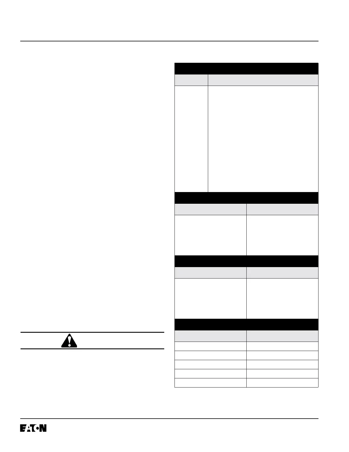
TABLE 2.5 FACTORY SET DEFAULTS
DIP SWITCH SETTINGS
Type Default Setting
S1: ON (Digitrip 3000 IMPACC Buffers)
S2: OFF (Program with Breaker Open
Only)
S3: OFF (Standard Relay Configuration -
OC/Instantaneous)
S4: OFF (Enable Remote Open/Close)
S5: OFF (Communications Close))
S6: OFF (Reserved)
S7: OFF (Reserved)
S8: OFF (Disable Download Setpoints)
S9: OFF (Manual Reset)
S10: OFF (Reserved)
PHASE SETTINGS
Type Default Setting
Curve Shape:
LDPU:
LDT:
SDPU:
SDT:
INST:
It
1.0
5 sec.
1.5
1.0 sec.
1.75
GROUND SETTINGS
Type Default Setting
Curve Shape:
LDPU:
LDT:
SDPU:
SDT:
INST:
It
0.5
5 sec.
0.75
1.0 sec.
1.0
MISCELLANEOUS SETTINGS
Type Default Setting
DISC: OFF
HILD: 10 sec.
FREQ: 60 Hz
CT P: 500
CT G: 500
 Loading...


