I.B. 17555C
Effective November 1999
Page 3
Thermal curves, plus ANSI and IEC inverse time overcur-
rent curves provide close coordination with both down-
stream and upstream protective devices. One Digitrip
3000 Protective Relay replaces the normal complement
of three or four conventional electro-mechanical overcur-
rent relays, an ammeter, a demand ammeter, an amme-
ter switch, and, in some situations, a lockout relay switch
(device 86). All Digitrip 3000 Protective Relays include a
built-in INCOM communication capability compatible with
the Cutler-Hammer PowerNet and IMPACC Systems.
1-3 FUNCTIONS/FEATURES/OPTIONS
The primary function of the Digitrip 3000 Protective Relay
is overcurrent protection. This is achieved by analyzing
the secondary current signals received from the switch-
gear current transformers. When predetermined current
levels and time delay settings are exceeded, the closing
of trip contact(s) is used to initiate breaker tripping.
The Digitrip 3000 Protective Relay operates from the sec-
ondary output of standard switchgear current transform-
ers rated at = 5 amperes. It is operator configured to fit
specific distribution system requirements. The current
transformer ratio information is programmed into Digitrip
3000 by setting pushbuttons located on the faceplate of
the relay. The phase and ground CT ratios can be inde-
pendently programmed over a range of 5:5 to 5000:5.
Refer to Table 2.4 for all available CT ratio settings.
Protective functions are also configured by using the
pushbuttons on the faceplate of the relay. These protec-
tive functions can be programmed with the circuit breaker
in the open or closed position. DIP Switch S2, located on
the rear of the relay, is used to control closed breaker set-
ting ability (Figure 1-3). Refer to Paragraph 2-2.2 and
Table 5.1 for additional information. Inverse time over-
current protection for the phase element cannot be dis-
abled. This insures that all phase protection cannot be
disabled. The relay also automatically exits the program
mode, if there is no programming activity for 2-1/2 min-
utes. Programming and test mode security is provided by
a sealable, hinged access cover on the front of the relay.
Direct reading displays indicate the value currently being
considered, while multi-colored LEDs indicate opera-
tional conditions and specific functions (Figure 1-1).
In addition to performing a continuous self-testing of
internal circuitry as a part of normal operation, all Digitrip
3000 Protective Relays include a front accessible, inte-
gral field testing capability. In the integral test mode, a
test current simulates an overload or short circuit condi-
tion, to check that all tripping features are functioning
properly. The test function is user selectable to trip or not
trip the breaker. Refer to Paragraph 2-1.5 for additional
information.
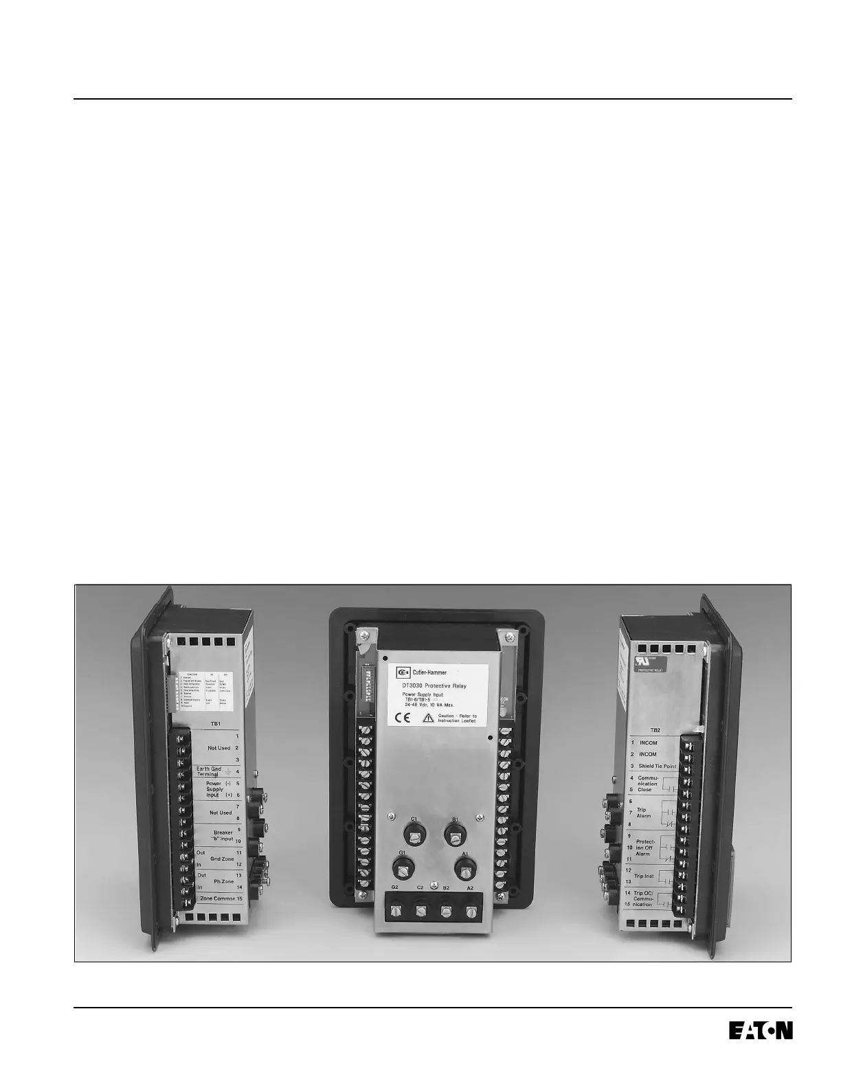
Fig. 1-2 Digitrip 3030 Protective Relay (Rear and Side Views)
 Loading...


