EasyManuals Logo

Eaton ELCB Series User Manual

Eaton ELCB Series
9 pages
To Next Page IconTo Next Page
To Previous Page IconTo Previous Page
Page #4 background imageLoading...
Page #4 background image
- 3 -
Input Points
Input No.
X0, X1
X2 ~
#1
Input point type
Digital input
Input type
DC (SINK or SOURCE)
Input current
24VDC, 5mA
Action level
Off → On
> 15VDC
On → Off
< 5VDC
Response
time
Off → On
25us
50us
On → Off
10us
20us
Filter time
Adjustable within 0 ~ 20ms in D1020 (Default: 10ms)
Output Points
Output point type
Relay-R
Transistor-T
Voltage specification
< 240VAC, 30VDC
5 ~ 30VDC
#2
Maximum
load
Resistive
2A/1 point (5A/COM)
0.5A/1 point (2A/COM)
Inductive
#3
12W (24VDC)
Lamp
20WDC/100WAC
2W(24VDC)
Response
time
Off → On
Approx. 10 ms
30us
On → Off
350us
#1: Please refer to I/O Terminal Layout for the maximum number of in puts and outputs
on each controller.
#2: UP, ZP must work with external auxiliary power supply 24VDC (-15% ~ +20%), rated
consumption approx. 1mA/point.
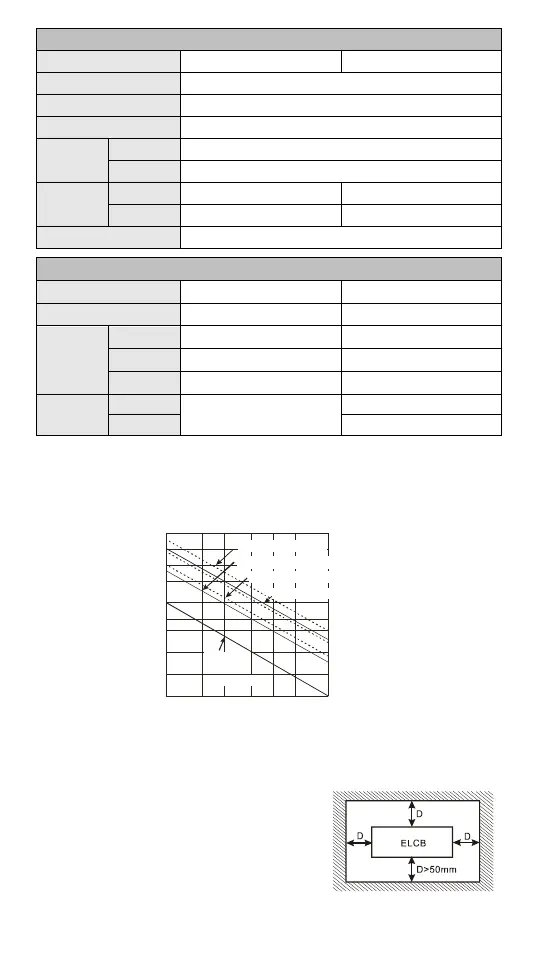
#3: See life curves (below)
Contact
Current(A)
0.5
0.1
0.2
50
0.3
0.7
1 2
200
300
500
100
1000
2000
3000
Operation(X10 )
3
120VAC Resistive
30VDC Inductive(t=7ms)
240VAC Inductive(cos 0.4)ψ=
120VAC Inductive(cos =0.4)ψ
30VDC
Inductive
(t=40ms)
Installation
Please install your controller in an enclosure with sufficient space around it
to allow proper ventilation, as shown in the figure.
DIN Rail Mounting: When mounting the
ELCB to 35mm DIN rail, be sure to use the
retaining clip to stop any side-to-side
movement of the ELCB and reduce the
chance of wires becoming loose. The
retaining clip is at the bottom of the ELCB.

Questions and Answers:

Question and Answer IconNeed help?

Do you have a question about the Eaton ELCB Series and is the answer not in the manual?

Eaton ELCB Series Specifications

General IconGeneral
BrandEaton
ModelELCB Series
CategoryController
LanguageEnglish

Related product manuals