EasyManuals Logo

Eaton EVER-Tap User Manual

Eaton EVER-Tap
52 pages
To Next Page IconTo Next Page
To Previous Page IconTo Previous Page
Page #19 background imageLoading...
Page #19 background image
1 2 3 4 5 6 7 8
VR VL
N
SL
S L
E3
E2
E1
E
CONTROL
V1
G
C2 C1
Source
Load
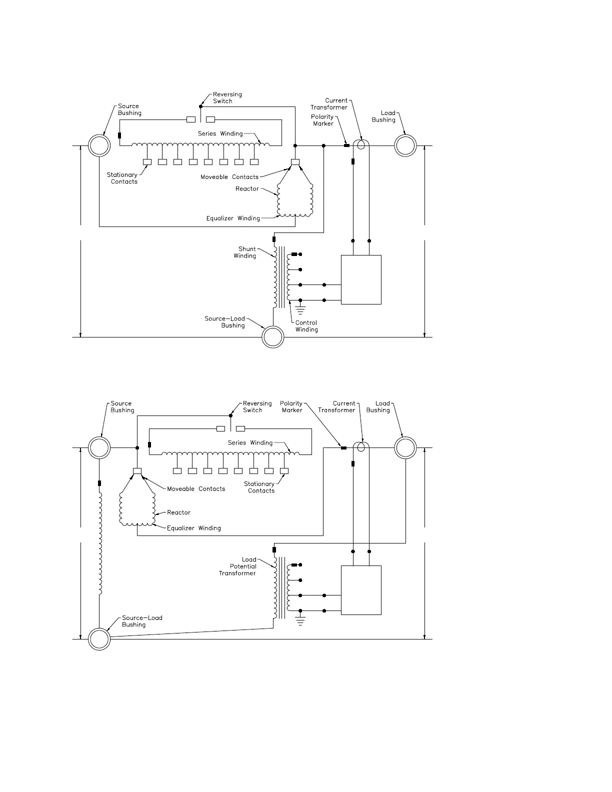
Figure 14. Power circuit—series winding located on the source-side, ANSI
®
Type B
1 2 3 4 5 6 7 8
VR VL
N
SL
S L
E3
E2
E1
E
CONTROL
V1
G
C2 C1
Source
Load
Figure 15. Power circuit—series winding located on the load-side, ANSI
®
Type A
15
VR-32 and EVER-Tap™ Voltage Regulator
InstallatIon, operatIon, and MaIntenance InstructIons MN225008EN June 2020

Questions and Answers:

Question and Answer IconNeed help?

Do you have a question about the Eaton EVER-Tap and is the answer not in the manual?

Eaton EVER-Tap Specifications

General IconGeneral
BrandEaton
ModelEVER-Tap
CategoryController
LanguageEnglish

Related product manuals