4. Connect a separate 120 Vac supply to the EXTERNAL
SOURCE terminals on the control front panel. Move
the control power switch to the EXTERNAL position to
operate the tap-changer.
ote:N For instruction on connecting the control to
an external source, see Service Information
MN225003EN, CL-7 Voltage Regulator Control
Installation, Operation, and Maintenance
Instructions.
5. Increase the voltage on the variac to 120 Vac. This will
provide 12 V on the series winding.
120 Vac x 10% regulation = 12 V
6. Calculate the change in volts per tap change as follows:
series winding volts = 12 = 0.75 V per step
16 steps 16
ote:N If 160 Vac is applied between the S and SL
bushings, the calculations in step 5 and step 6 are
computed, you will see that a 1.0 volt difference
between steps will result. Doing this will simplify
the ratio check.
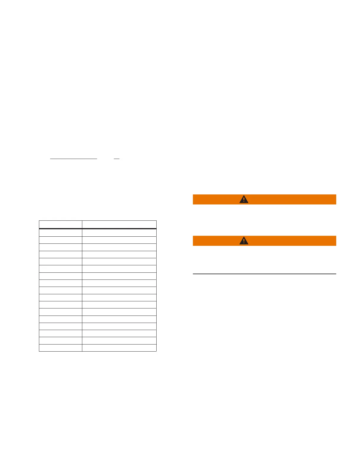
Table 8. Typical meter readings with 120 Vac
connected between the S and SL bushings
Lower Raise
16L - 108.0 16R - 132.0
15L - 108.75 15R - 131.25
14L - 109.5 14R - 130.5
13L - 110.25 13R - 129.75
12L - 111.0 12R - 129.0
11L - 111.75 11R - 128.25
10L - 112.5 10R - 127.5
9L - 113.25 9R - 126.75
8L - 114.0 8R - 126.0
7L - 114.75 7R - 125.25
6L - 115.5 6R - 124.5
5L - 116.25 5R - 123.75
4L - 117.0 4R - 123.0
3L - 117.75 3R - 122.25
2L - 118.5 2R - 121.5
1L - 119.25 1R - 120.75
Neutral 120
7. Operate the tap-changer with the control switch
through all 32 steps from 16 Raise to 16 Lower.
Record the voltmeter reading at each tap position. The
change in voltage should be almost the same between
each step (± 0.10 volts). If a substantial difference in
any reading exists, then there is a problem with the
windings or their connection. Readings will be the
same with or without the equalizer winding.
ote:N On a type B regulator, the difference between
the taps will be slightly less than calculated as
the regulator is tapped toward 16 Lower. This is
normal and inherent in the design of the type B
regulator.
Questions about the described procedure may be directed
to your Eaton representative.
Voltage regulator potential transformer ratio test
Purpose
The purpose of this test is to verify proper potential
transformer ratio.
Required equipment
Voltmeter
120 V variable power supply
Appropriate cable leads
Calculator
Procedure
WARNING
Hazardous Voltage. This procedure must only be
performed on a regulator that has been removed from
service. Failure to comply can cause serious injury or
death.
WARNING
Hazardous Voltage. When troubleshooting energized
equipment, protective gear must be worn to avoid
personal contact with energized parts. Failure to comply
can cause serious injury or death.
1. Remove the unit from service as described in
“Removal from service” on page 11.
2. Open the back-panel knife switch marked V1.
3. Note the correct PT ratio as given for the pinned Load
Volts on the nameplate under the Internal PT Ratio
column. The tap setting of the PT can be verified by
inspecting the tap-changer terminal board connection
through the hand-hole on the regulator cover. The
tap-changer terminal board is located on the top of the
tap-changer under oil. The connection will be E1, E2
and E3; this should correspond to the PT ratio for the
voltage pinned on the nameplate.
4. With the regulator in the neutral position, connect 120
Vac between the S (Source) and the SL (Source Load)
bushings.
5. Using the formula below, determine the expected
output voltage of the PT.
Expected Voltage = 120 Vac/PT Ratio
31
VR-32 and EVER-Tap™ Voltage Regulator
InstallatIon, operatIon, and MaIntenance InstructIons MN225008EN June 2020