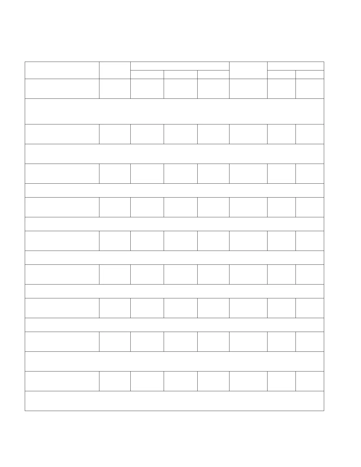
Table10. Function codes (continued)
Parameter
Unit of
Measure
Security Level
Default Value
Key Entry Limit
To Read To Write To Reset Low High
813 IEC104 Single
Command Op Mode
SBE
--- View Modify NA SBE NA NA
•This is the Com 1 setting that defines if the control will respond directly (Direct mode)
to Single Command Operation commands or if a "select" is required before "execution" (SBE
mode).
•The available options are: Direct; SBE.
813 IEC104 Select
Before Exec Time
XXXXX mSec
MilliSec View Modify NA 5000 0 65535
•This is the Com 1 setting that determines the amount of time that can elapse between a
"select" and "execute" command for Single Command Operations in systems that employ a
select-before-execute mode.
813 IEC104 Response
Timeout (t1)
XXXXX Seconds
Seconds View Modify NA 15 1 255
•This is the Com 1 setting for the time-out value for the transmission of data or test
messages.
813 IEC104 Ack/No
Data (t2)
XXXXX Seconds
Seconds View Modify NA 10 1 255
•This is the Com 1 setting for time-out before sending an ACK APDU if no data ACKs are
received.
813 IEC104 Idle
Test (t3)
XXXXX Seconds
Seconds View Modify NA 20 1 255
•This is the Com 1 setting for the amount of time allowed to lapse before a test APDU is
generated.
813 IEC104 Max
Transmit (k)
XXXXX
--- View Modify NA 12 1 32767
•This is the Com 1 setting for the maximum number of unacknowledged data frames that are
allowed to be in transit.
813 IEC104 Max
Receive (w)
XXXXX
--- View Modify NA 8 1 32767
•This is the Com 1 setting for the maximum number of data frames to wait before
acknowledging if no data ACKs are received (w should normally not exceed 2 K/3).
813 IEC104 User Map
Selection
CL-7 Default
--- View Modify NA
CL-7
Default
NA NA
•The selection of the active IEC104 map for Com 1. The available options are: User 1;
User 2; CL-7 Default; CL-7 Default Events; CL-7 Advanced; CL-6 Default; CL-6 Default
Events; CL-7 3Ph Default; CL-7 3Ph Default Evt; CL-7 3Ph Advanced.
815 2179 Master
Address
XX
--- View Modify NA 0 0 31
•This is the Com 1 setting for the address, from 0 to 31, of the master station
controlling and polling the RTU.
•Configuration parameters for 2179 are displayed when the protocol is available.
108
INSTALLATION, OPERATION, AND MAINTENANCE INSTRUCTIONS MN225003EN April 2018
CL-7 Voltage Regulator Control

 Loading...


