IM02602002E
www.eaton.com Page 13-1
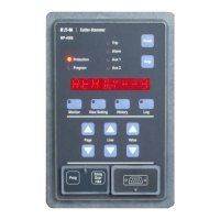
MP-3000
Relay maintains the same electrical and operating specications as
the standard MP-3000. Specications for the Drawout connectors are
shown in Table 13.2.
Description Value
Make/Break Rating
10 A @ 240 Vac nominal
0.25 A @ 280 Vdc
maximum
Terminal Wire Gauge
No. 14 to No. 10 AWG
(2.5 mm
2
to 6.0 mm
2
)
Screw Torque Requirements 18 lb-in. (2.0 Nm)
The MP-3000 Drawout consists of two assemblies: an inner chassis
and an outer chassis. The outer chassis consists of an aluminum
housing with terminal blocks, a molded plastic ange with quick-re-
lease actuators, and a locking mechanism.
The drawout terminal blocks feature self-shorting, or short-before-
break set of contacts, for CT connections that maintain circuit continu-
ity when the device is removed. These self-shorting contacts prevent
damaging voltages from existing across the current transformer
windings.
An extra set of self-shorting terminals can be used to keep the motor
running while the relay is out of its case, or to provide a No Protection
Alarm (refer to Subsection 13.4 for more information).
The following material supplements installation information provided in
Sections 6.1.1 through 6.1.3 and Figures 6.1 and 6.3. Refer to these
sections and gures rst.
The Drawout Case uses the same panel cutout as the xed mount
MP-3000, IQ1000II, and IQ1000. When mounting the Drawout Case
in a panel, it is necessary to prepare a cutout for the device per Figure
13.1. If a standard IQ cutout exists, no additional panel setup is re-
quired. The Drawout mounts securely in an existing 6-hole or 10-hole
cutout.
Before mounting the Drawout Relay, check the contents of the box
against the parts listed in Table 13.3 and shown in Figure 13.2.
MP-3000 Drawout Inner Chassis 1
MP-3000 Drawout Outer Case 1
Outer Flange 1
Mounting Hardware – #10-32 nuts and
lock washers
6 each
MP-3000 Instruction CD
1
-
-
This section describes the Drawout Case option for the MP-3000
Motor Protection Relay.
The basic operation of the MP-3000 relay is applicable to all styles
of the drawout case. Table 13.1 lists the Drawout Case versions.
MP-3000 Drawout Relay, 5 A,
No Communications
MP-3011
MP-3000 Drawout Relay, 5 A, Built-in
INCOM Communications
MP-3012
MP-3000 Drawout Relay, 5 A,
Modbus
MP-3013
MP-3000 Drawout Relay, 5 A,
DeviceNet
MP-3014
MP-3000 Drawout Relay, 1 A,
No Communications
MP-3111
MP-3000 Drawout Relay, 1 A, Built-in
INCOM Communications
MP-3112
MP-3000 Drawout Relay, 1 A,
Modbus
MP-3113
MP-3000 Drawout Relay, 5 A,
DeviceNet
MP-3114
MP-3000 Drawout Outer Chassis, for
Use with No Communicatiions or IN-
COM Communications Inner Chassis
MP3X11-OC
MP-3000 Drawout Outer Chassis, for
Use with Modbus Communicatiions
Inner Chassis
MP3X13-OC
MP-3000 Drawout Outer Chassis, for
Use with DeviceNet Communicatiions
Inner Chassis
MP3X14-OC
The Quick Release Drawout Case permits the relay to be removed
from service without disconnecting the wires. The MP-3000 Drawout

 Loading...


