11
Instruction Leaet IL01301008E
Effective June 2015
Installation and removal instructions for Series NRX
undervoltage release, shunt trip, and overcurrent
trip switch in left accessory tray
EATON www.eaton.com
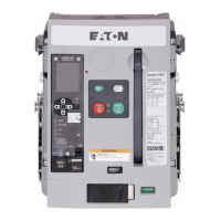
Step 4: Rotate the top end of the terminal block in until it engages
the appropriate flexible mounting tab at the top of the mounting
plate with a clicking sound.
4
3
1
5
7
9
1
1
13
15
17
19
21
23
25
27
OT1M
OT2B
OT2M
ALM1
ALM2
ALMC
OT2C
OT1B
OT1C
N2
G2
G1
N1
SGF1
AGND
CMM2
CMM1
+24V
SGF2
CMM4
CMM3
ZOOM
ZOUT
UV2
UV1
6
8
10
12
14
16
18
20
22
24
26
28
30
32
34
14
13
Figure 41. Step 4
m IMPORTANT
TO REMOVE RIGHT AND LEFT ACCESSORY TRAYS OR ANY OTHER
ELECTRICAL ACCESSORY, THE APPROPRIATE ACCESSORY CONNECTOR
PLUG MUST FIRST BE DISCONNECTED.
Step 5: To remove an accessory plug on a fixed circuit breaker, the
appropriate fixed secondary terminal block must first be removed.
To remove a fixed secondary terminal block, lift up on the small
flexible mounting tab at the top of the fixed terminal block mounting
plate, and rotate the terminal block out in the opposite direction
shown in Step 4. Once the terminal block is removed, the accessory
connector plug can be unplugged from the bottom of the terminal
block. Refer to Item 2 and Figure 37 under the heading “General
information” in this section for detailed assistance with the removal.
Drawout breaker connections
Proceed with the following three steps.
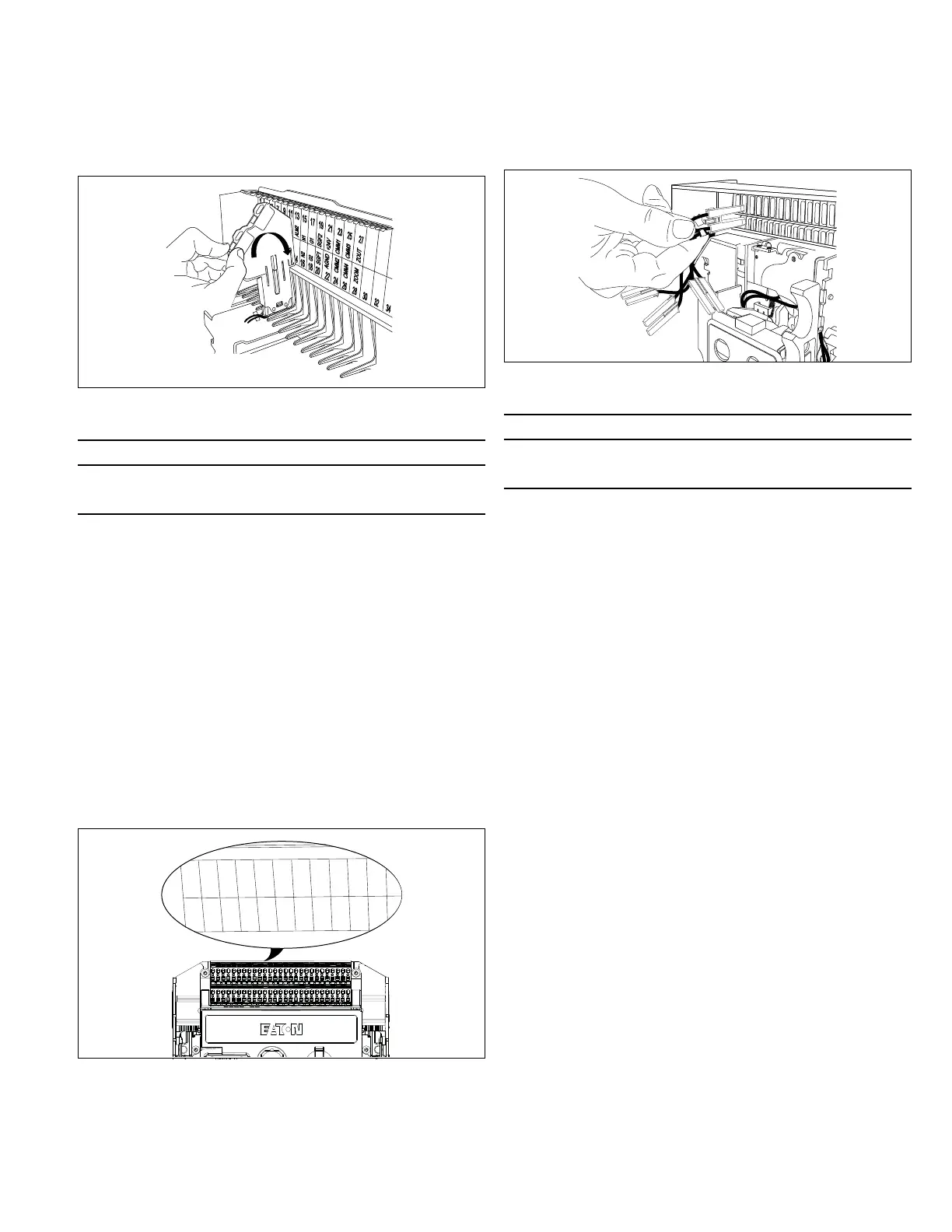
Step 1: Become familiar with the drawout secondary plug housing
where secondary connections are made.
ote:N Secondary connection points have numerical and descriptive laser-
etched identifications on top of the housing directly matching the plug-in
locations below.
1
2
4
3
5
6
7
8
9
10
12
14
16
11
13
15
17
18
19
20
21
22
CMM2
AGND
SGF1
G2
N2
N1
ALM2
ALM1
OT2M
OT2B
OT1M
UV2
ST2
ST1
UV1
OT1C
OT1B
OT2C
ALMC
G1
SGF2
+24V
CMM1
Figure 42. Step 1
Step 2: Plug accessory connector plug into position in the
secondary plug housing matching the laser-etched identification
on top of the housing.
1
2
Figure 43. Step 2
m IMPORTANT
TO REMOVE RIGHT AND LEFT ACCESSORY TRAYS OR ANY OTHER
ELECTRICAL ACCESSORY, THE APPROPRIATE ACCESSORY CONNECTOR
PLUG MUST FIRST BE DISCONNECTED.
Step 3: To remove an accessory connector plug on a drawout circuit
breaker, unplug it from its secondary plug housing. Refer to Item2
and Figure 37 under the heading “General information” in this
section for detailed assistance with the removal.

 Loading...