3
Instruction Leaet IL01301008E
Effective June 2015
Installation and removal instructions for Series NRX
undervoltage release, shunt trip, and overcurrent
trip switch in left accessory tray
EATON www.eaton.com
Table 1. Shunt trip ratings
Control
voltage Frequency
Operational
voltage
(range 70–110%)
Inrush/
continuous
power
consumption (VA)
Opening
time (ms)
24 DC 17–26 400/2 25
48 DC 34–53 500/3 25
60 DC 42-66 500/4 25
110–127 50–60 Hz 77–140 800/8 25
110–125 DC 77–138 800/8 25
208–240 50–60 Hz 146–264 850/8 25
220–250 DC 154–275 850/8 25
Table 2. Undervoltage release ratings
Control
voltage
Frequency
Operational
voltage
(range
(85–110%)
Dropout
voltage
range
(35–60%)
Inrush/
continuous
power
consumption (VA)
Opening
time (ms)
24 DC 20–26 8–14 425/2 50
32 DC 27–35 11–19 N/A 50
48 DC 41–53 17–29 750/3 50
60 DC 51-66 21-36 825/4 50
110–127 50–60 Hz 94–140 44–66 1150/8 50
110–125 DC 94–138 44–66 1150/8 50
208–240 50–60 Hz 177–264 84–125 1200/8 50
220–250 DC 187–275 88–132 1200/8 50
380–415 AC 323–457 145–228 N/A 50
480 AC 408–528 168–288 N/A 50
600 AC 510–660 210–360 N/A 50
Table 3. Overcurrent trip switch ratings
Control
voltage Frequency
Contact
rating (amperes)
250 50–60 Hz 10
125 DC 0.5
250 DC 0.25
Section 2: Installation of undervoltage
release and/or shunt trip in left
accessory tray
Proceed with the following 13 steps.
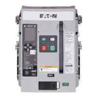
Step 1: Remove the four screws holding the front cover in place
(two on each side of the cover).
Figure 4. Step 1 (NF frame shown)
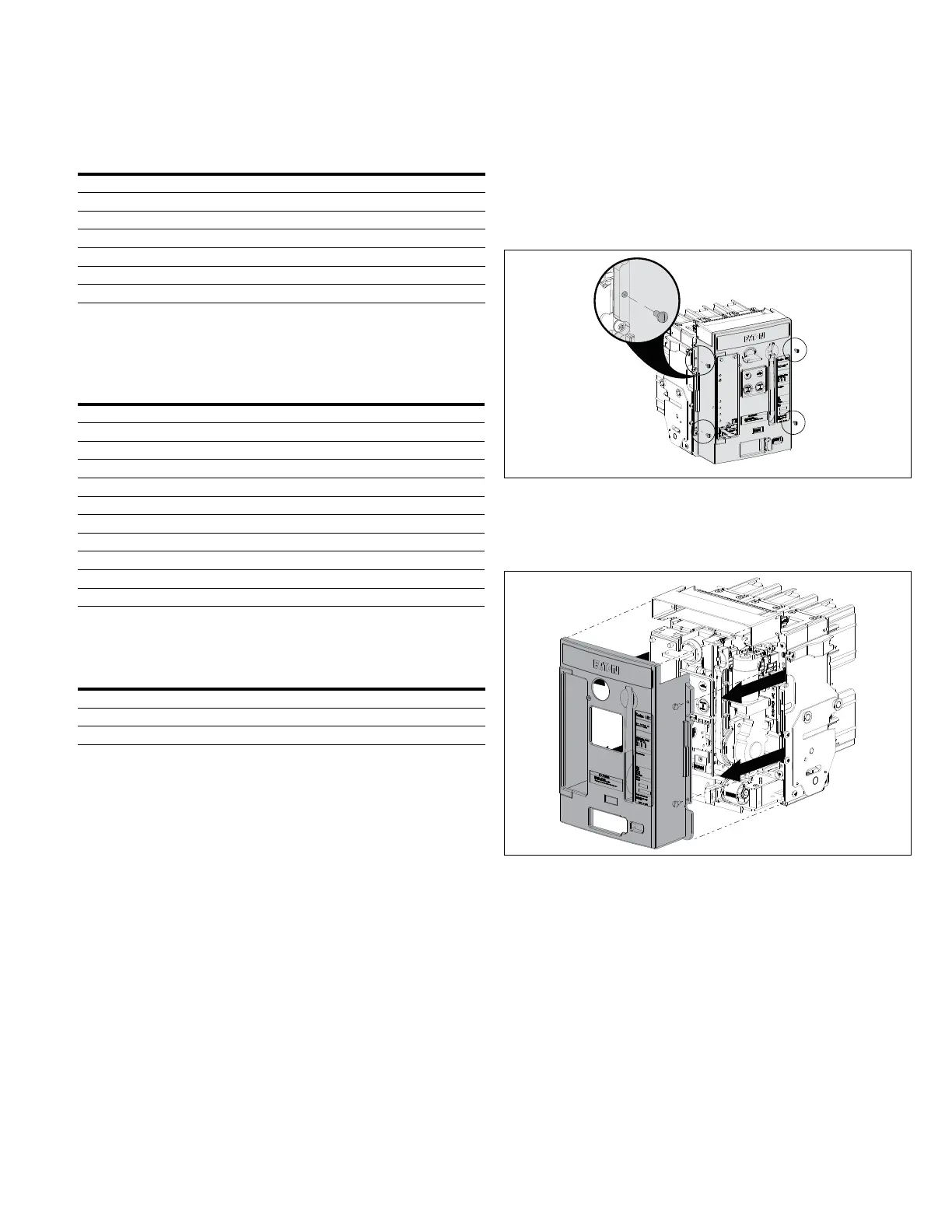
Step 2: Remove the front cover. Pull down on the charging handle to
simplify removal.
Figure 5. Step 2 (NF frame shown)

 Loading...