7
Instruction Leaet IL01301008E
Effective June 2015
Installation and removal instructions for Series NRX
undervoltage release, shunt trip, and overcurrent
trip switch in left accessory tray
EATON www.eaton.com
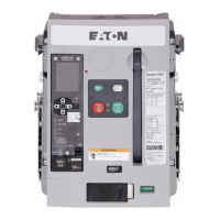
Thumb tab
ST
UVR
Figure 21. Step 3 (RF frame shown)
Step 4: Position the tray as shown and remove secondary leads
from behind molded retaining tabs of the accessory being removed.
Pull back on the locking tab to unlock the UVR or ST from the left
accessory tray.
Accessory locking tab
ST
UVR
Figure 22. Step 4 (NF frame shown)
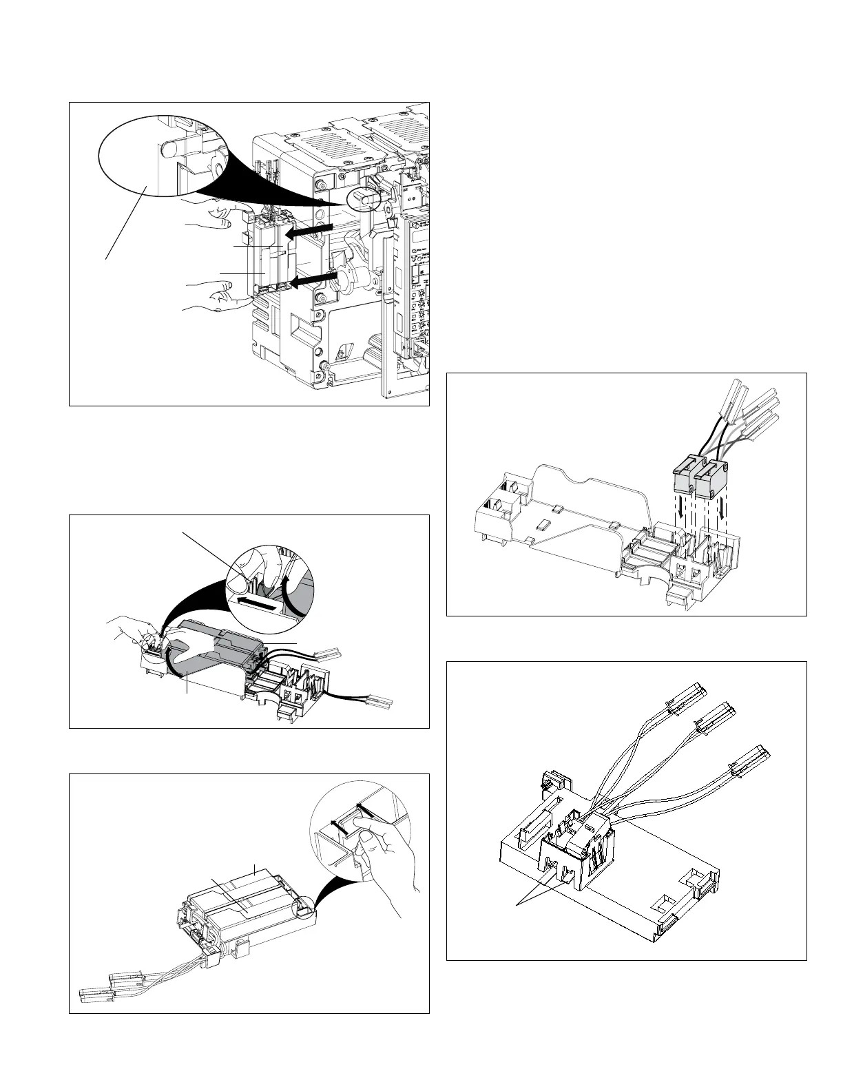
ST
UVR
Figure 23. Step 4 (RF frame shown)
Step 5: Remove the UVR or ST by lifting it upward and out.
Step 6: Repeat Step 4 and Step 5 if the other accessory is also to
be removed.
Step 7: If the tray will have a new ST and/or UVR installed, follow
Step 4 through Step 13 of Section 2. If not, just complete Step 10
through Step 13 of Section 2.
Section 4: Installation of overcurrent trip in
left accessory tray
Proceed with the following seven steps.
Step 1: If necessary, remove the front cover from the breaker by
first performing Step 1 and Step 2 of Section 2.
Step 2: Position the left accessory tray as shown and bring the
two OTS switches down for insertion into the left accessory tray.
Carefully push the OTS switches down until they lock into place.
Figure 24. Step 2 (NF frame shown)
Metal lever
Figure 25. Step 2 (RF frame shown)
ote:N For the RF frame, the metal lever must pass through the opening
before locking switch into place.

 Loading...