8
Instruction Leaet IL01301008E
Effective June 2015
Installation and removal instructions for Series NRX
undervoltage release, shunt trip, and overcurrent
trip switch in left accessory tray
EATON www.eaton.com
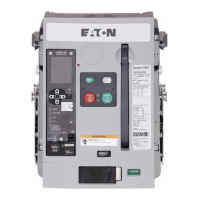
Step 3: Route the six secondary leads and the three connectors
forward and to the right out the end of the accessory tray for the
NF frame. For the RF frame, route the leads out as shown.
Figure 26. Step 3 (NF frame shown)
Figure 27. Step 3 (RF frame shown)
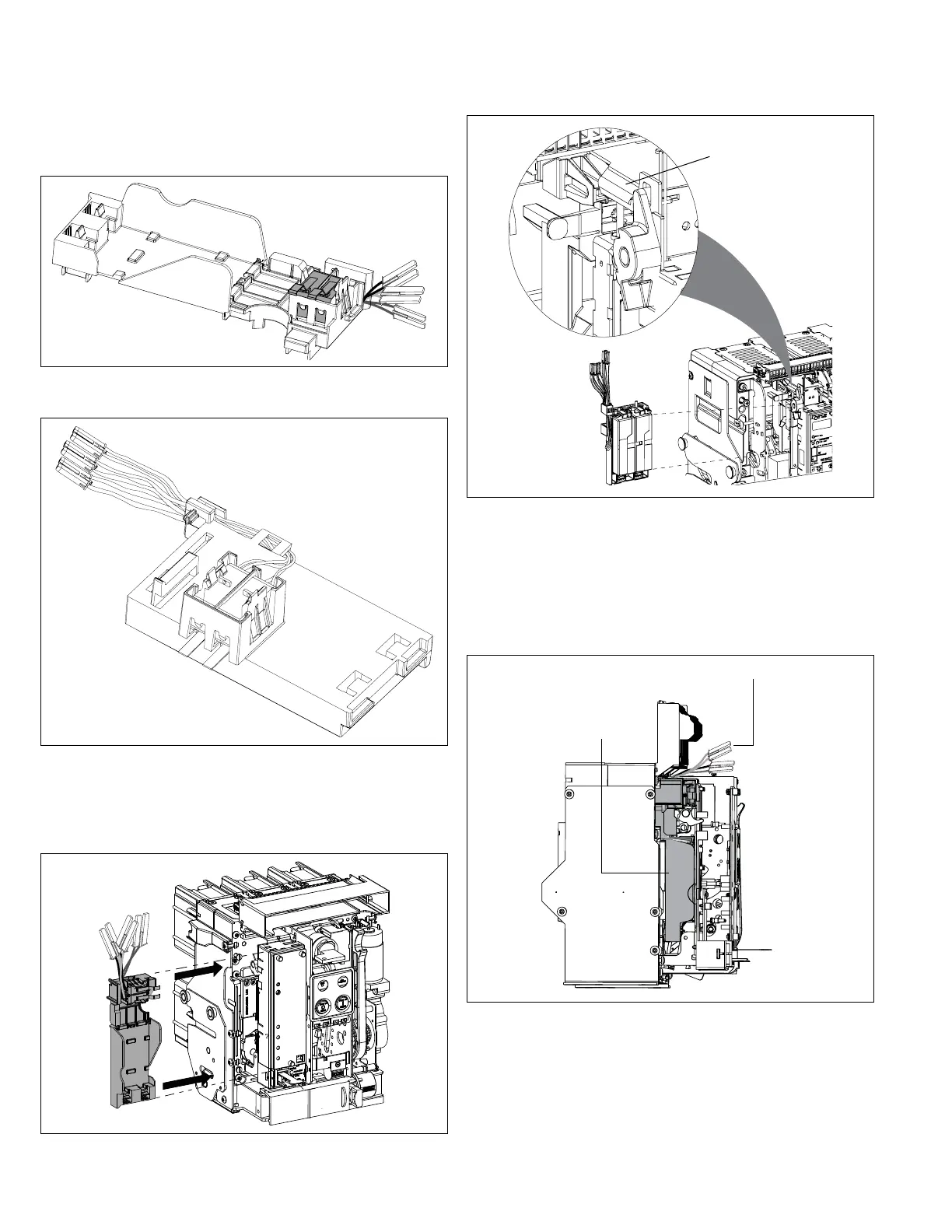
Step 4: Place the left accessory tray with the installed OTS switches
back to its original position as shown. Be careful not to bind
secondary wires or connector plugs.
Figure 28. Step 4 (NF frame shown)
Trip unit
interlock plate
Figure 29. Step 4 (RF frame shown)
ote:N The proper routing of leads will prevent the wires from being pinched
by the trip unit interlock plate in the RF frame breaker.
Step 5: The installed left accessory tray should look as shown in
Figure 30 with secondary leads extending out behind the trip unit
mounting plate location. Secondary connections can now be made.
Accessory tray
installed
Secondary connectors
Figure 30. Step 5 (NF frame shown)
Step 6: Make the appropriate secondary connections as outlined
in Section 6. If necessary, bundle secondary wires using industry-
accepted wire tie practices.
Step 7: Replace the front cover and secure it in place with the four
mounting screws previously removed in Step 1.

 Loading...