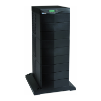
FIELD INSTALLED UPM INSTALLATION PLAN AND UNPACKING
Power Xpert 9395P Field Installed UPM Mechanical Installation Manual S P-164000503 Rev 1
3-2
Table 3‐1. FI-UPM Cabinet Maximum Weight
Model
Maximum Weight
kg (lb)
Shipping Installed
Power Xpert 9395P FI-UPM 496 (1094) 471 (1037)
The FI-UPM cabinet uses forced air cooling to regulate internal component
temperature. Air inlets are in the front of the cabinet and outlets are in the top. Allow
clearance in front of and above each cabinet for proper air circulation. The clearances
required around the FI-UPM cabinet are shown in Table 3‐2. Dimensions are in
millimeters (inches).
Table 3‐2. FI-UPM Cabinet Clearances
From Top of Cabinet 457.2 mm (18”) minimum clearance for ventilation
From Front of Cabinet 914.4 mm (36”) working space
From Back of Cabinet None Required
From Right Side of Cabinet None Required
From Left Side of Cabinet None Required
The basic environmental requirements for operation of the FI-UPM are:
S Ambient Temperature Range: 0–40°C (32–104°F)
S Recommended Operating Range: 20–25°C (68–77°F)
S Maximum Relative Humidity: 95%, non-condensing
The FI-UPM ventilation requirements are shown in Table 3‐3.
Table 3‐3. FI-UPM Air Conditioning or Ventilation Requirements During Full Load Operation
Rating Input/Output Voltage
Heat Rejection
kW (1000 BTU/hr)
Ventilation Required for
Cooling Air Exhaust
225 kVA
480/480 7.9 (27.1)
Approximately
950 liter/sec
(2000 CFM)
250 kVA
480/480 9.3 (31.9)
275 kVA
480/480 10.6 (36.1)
300 kVA
480/480 10.6 (36.1)

 Loading...


