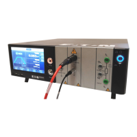
Do you have a question about the Eaton SEFELEC 56-S and is the answer not in the manual?
Eaton guarantees devices are free of manufacturing and packaging faults.
Provides essential safety instructions for using the measurement device before and after operation.
Specifies the overvoltage category (CAT II) for supplying the device.
Defines the pollution degree (Pollution 2) related to condensation.
Classifies the device as Class I, connected to protective ground.
Lists general electrical and physical characteristics of the SEFELEC 5x range devices.
Details output voltage, current, stability, and accuracy for dielectric strength tests.
Details precautions for working on electrical devices, emphasizing connection to ground and high voltage light status.
Describes sectioning of equipment by power cord and the presence of double safety loops.
Explains the double safety loop function and its role in electromechanical cut-off of high voltage.
Discusses safety loop usage and optional Red/Green light for dangerous voltages.
Lists crucial precautions for device usage, including software control and capacitor discharge.
Details the correct installation of accessories and connection of the mains power cord.
Provides step-by-step instructions for fitting the SEFELEC 5x range device into a bay.
Explains how to turn on the device and the initial screen sequence.
Explains how to adjust display brightness and colors via cursors in the General settings menu.
Details how to choose different sound options for device actions in the General settings menu.
Instructs on setting the device's time and date, including format selection.
Shows how to access system information like firmware version, model, and serial number.
Guides on changing user levels (Administrator, Technician, Operator) and password management.
Explains how to select and configure communication interfaces like Ethernet, RS232, GPIB, and PLC.
Details the process to restore the device to its default settings via the General settings menu.
Explains how to store test settings and measurement results in the device's internal memory.
Provides essential safety warnings and instructions for connecting components for insulation resistance measurement.
Details precautions for accurate insulation resistance measurements, including shielding and operator proximity.
Describes fault detection modes: Delta I, IMAX, and combination modes.
Explains how to adjust current thresholds (IMAX, IMIN, Delta I) for fault detection.
Provides safety warnings and instructions for connecting components for dielectric strength testing.
Details precautions for dielectric strength measurements, including discharge mode and device checking.
Provides safety warnings and instructions for connecting components for multi-slope dielectric strength tests.
Details precautions for multi-slope dielectric strength measurements, including discharge and device checking.
Provides safety warnings and instructions for connecting components for ground continuity resistance measurement.
Details precautions for ground continuity measurement, emphasizing 4-wire method and cable handling.
Guides on executing a pre-defined measurement sequence.
Explains the measurement-discharge cycle using PLC control signals.
Provides recommendations for securing the SEFELEC 5x range devices against cyber threats.
Emphasizes the importance of physical security to prevent unauthorized access and disruption.
Details best practices for logical access, including unique accounts and privilege restrictions.
Provides best practices for securing network communication, including segmentation and encryption.
Highlights the importance of strict management for remote access to maintain ICS security.
Recommends deploying adequate malware defenses to protect the product and platforms.
Provides best practices for secure maintenance, including firmware updates and patches.
Guides on configuring the Ethernet connection on the SEFELEC 5x device, including DHCP and IP settings.
Explains the process of measuring insulation resistance and its purpose.
Details precautions for insulation resistance measurements, emphasizing parasite leakages and shielding.
Explains the purpose and principle of dielectric strength tests.
Explains common leakage current control modes like IMAX and Delta I for breakdown detection.
Explains the purpose and principle of ground continuity measurement.
Details precautions for ground continuity measurement, emphasizing 4-wire method and probe handling.
Details the C5 safety connector, its pinout, and connection examples for safety loops and indicators.
Discusses device maintenance, highlighting that special maintenance is not required except for calibration.
| Brand | Eaton |
|---|---|
| Model | SEFELEC 56-S |
| Category | Test Equipment |
| Language | English |


