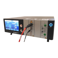
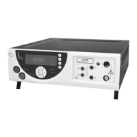
Do you have a question about the Eaton SEFELEC 506-S and is the answer not in the manual?
Provides critical safety instructions for using the SEFELEC 5x range devices.
Specifies the overvoltage category (CAT II) for supplying power to the device.
Defines the pollution degree (Pollution 2) related to conductive pollution by condensation.
Indicates the safety class (Class I) concerning protective ground connection.
Details technical specifications for dielectric strength, insulation, and ground continuity measurements.
Emphasizes precautions for working with electrical devices, including grounding and high voltage.
Describes safety features like power cord sectioning and double safety loops for secure operation.
Explains the procedure for powering on the device and the initial display sequence.
Guides users on selecting communication interfaces like Ethernet, RS232, or GPIB.
Explains how to save test settings and measurement results in the device's internal memory.
Details how to set the measurement duration using Auto or Permanent modes.
Explains how to set the DC voltage for insulation resistance measurements.
Guides on setting Rmin and Rmax thresholds for PASS/FAIL determination.
Provides instructions and warnings for connecting components for measurement.
Lists precautions to observe during insulation resistance measurements for accuracy and safety.
Explains common error messages and their meanings during measurements.
Explains how to adjust test time using Auto, Manual, or Permanent modes.
Guides on setting the voltage for dielectric strength tests (AC or DC).
Describes Delta I and IMAX modes for detecting breakdowns during tests.
Details how to set IMAX, IMIN, and Delta I thresholds for fault detection.
Provides instructions and warnings for connecting components for multi-slope tests.
Lists precautions to observe during multi-slope dielectric strength tests.
Explains common error messages specific to multi-slope dielectric strength tests.
Details how to set measurement duration for ground continuity tests.
Explains how to set the current level for ground continuity measurements.
Guides on setting resistance or voltage drop thresholds for PASS/FAIL results.
Lists precautions for low resistance measurements to ensure accuracy and safety.
Offers best practices for securing the SEFELEC 5x range against cyber threats.
Lists crucial precautions to take during insulation resistance measurements.
Lists precautions for low resistance measurements using the 4-wire method.
| Brand | Eaton |
|---|---|
| Model | SEFELEC 506-S |
| Category | Test Equipment |
| Language | English |


