16
Instruction Book IB182312EN June 2016 www.eaton.com
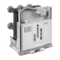
50/75/150 VCP-W
Selectable Ground and Test Device
g. Repeat steps ‘f’ for the remaining selector blades of the SG&T
terminals.
h. Replace the removable barriers into their respective retainers
before proceeding to the next step (Figure 5.3).
i. Close the terminal set door and secure it with the special
Kirk™ lock bolt (if so equipped.) The Kirk™ Lock bolt is pushed
through the door hasp and into the Kirk™ lock itself. Turn the
Kirk™ key to retain the special bolt and release the Kirk™ key
from the lock cylinder. (Figure 5.1).
j. If the other set of terminals are to be accessed and grounded,
start at ‘a’ above to ground the other set of terminals, if the
SG&T is the six terminal type.
k. When all tests are complete, return the selector blades to the
neutral position and re-install the removable barriers.
l. The SG&T may now be removed from the switchgear circuit
breaker compartment using the removal procedure in Section
5.5.
DANGER
FAILURE TO RETURN THE SELECTABLE BLADES TO THE NEUTRAL
POSITION INSIDE THE SG&T AFTER TESTING IS COMPLETE WILL CAUSE
DEATH, SERIOUS INJURY, AND/OR PROPERTY DAMAGE. A THREE
PHASE BOLTED FAULT WILL OCCUR IF THE CIRCUIT IS INADVERTENTLY
ENERGIZED.
5.5 INSERTION PROCEDURE
CAUTION
THE MAIN SWITCHGEAR BUS AND SWITCHGEAR LOAD CONNECTIONS
ARE CONNECTED WHEN THIS GROUND AND TEST DEVICE IS RACKED TO
THE ‘CONNECTED’ POSITION. ALL PRIMARY CIRCUITS MUST BE FULLY
DE-ENERGIZED, LOCKED AND TAGGED OUT TO PREVENT INADVERTENT
ENERGIZATION. CONFIRM THAT LINE AND LOAD PRIMARY CIRCUITS
ARE NOT BACKFED THROUGH SECONDARY CONTROL CIRCUITS SUCH AS
POTENTIAL TRANSFORMERS OR CONTROL POWER TRANSFORMERS. THIS
GROUND AND TEST DEVICE MUST BE OPERATED ONLY WITH A WELL
MAINTAINED AND CERTIFIED ‘HOT STICK’.
DANGER
FAILURE TO REMOVE ALL SOURCES OF POWER FROM THE CIRCUIT
BREAKER COMPARTMENT BEING GROUNDED WILL RESULT IN PERSONAL
INJURY AND PROPERTY DAMAGE. APPROPRIATE PERSONAL PROTECTIVE
EQUIPMENT (PPE) MUST BE IN PLACE PRIOR TO OPERATING THIS SG&T.
WARNING
EXAMINE THE INSIDE OF THE CELL BEFORE INSERTING THE SG&T FOR
EXCESSIVE DIRT OR ANYTHING THAT MIGHT INTERFERE WITH THE SG&T
TRAVEL.
KEEP HANDS OFF THE TOP EDGE OF THE FRONT BARRIER WHEN PUSHING
A SG&T INTO A CELL. FAILURE TO DO SO COULD RESULT IN BODILY
INJURY, IF FINGERS BECOME WEDGED BETWEEN THE SG&T AND THE
CELL. USE BOTH FULLY OPENED HANDS FLAT ON THE FRONT OF THE SG&T
TO ADVANCE INTO THE STRUCTURE.
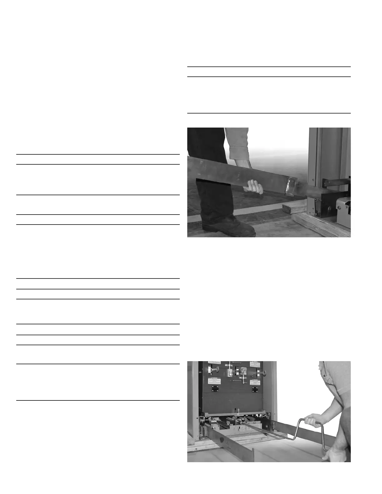
If the VCP-W SG&T is being inserted into an upper compartment
or will be positioned in a lower compartment without the use of a
drawout ramp or dockable dolly, the extension rails must first be
put in position. Carefully engage the left and right extension rails to
the fixed structure rails and ensure they are properly seated in place
(Figure 5.9). Once the extension rails are properly in place, the SG&T
can be carefully loaded on the extension rails using an overhead lifter
and lifting yoke. Remove the lifting yoke when the SG&T is securely
seated on the extension rails.
Figure 5.9. Inserting Guide Rails
Figure 5.10. Racking the SG&T Device
Push the SG&T into the compartment until the Disconnect/Test
position is reached as confirmed by a metallic sound of the racking
latch engaging the racking nut (Figures 5.10). Once the SG&T is in
the Disconnect/Test position, the extension rails can be removed.
WARNING
DO NOT USE ANY TOOL OTHER THAN THE RACKING-IN CRANK PROVIDED
TO LEVER THE SG&T FROM TEST OR CONNECTED POSITIONS. CORRECT
OPERATION OF SOME OF THE INTERLOCKS IS DEPENDENT ON USE OF THE
PROVIDED RACKING CRANK. PERSONAL INJURY OR EQUIPMENT DAMAGE
COULD RESULT FROM THE USE A TOOL OTHER THAN THE PROPER
RACKING-IN CRANK.
To move the VCP-W SG&T to the CONNECTED position, engage
the racking-in crank with the structure mounted racking shaft
(Figure 5.10). Turn the racking-in crank in a clockwise direction and
the SG&T will move slowly toward the rear of the structure. When
the SG&T reaches the CONNECTED position (Figure 5.11), it will
become impossible to continue turning the racking-in crank. The
CONNECTED position will also be indicated by a red flag indicator
just below the racking device.
5.5 REMOVAL PROCEDURE
To remove the SG&T device from the CONNECTED position, engage
the racking handle onto the circuit breaker compartment mounted
racking shaft. Turn the racking handle counterclockwise until the
SG&T reaches the ‘disconnect/test’ position. When the ‘disconnect/
test’ position is reached, it will not be possible to turn the racking
handle any further. The ‘disconnect/test’ position is indicated by a
green indicator below the racking device.

 Loading...