15
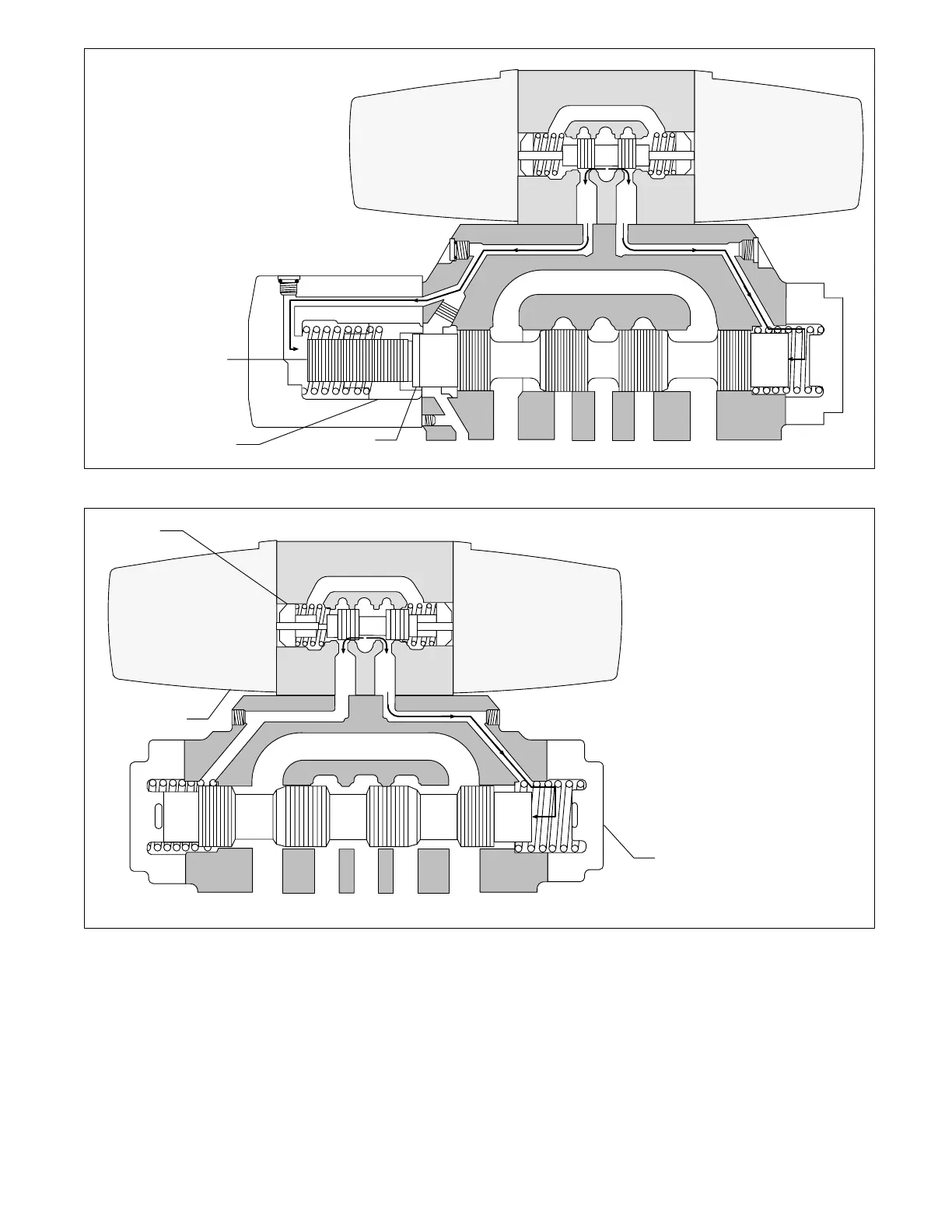
Shoulder
of Piston
Figure 7. Pressure Centered “D” Model
P
B
Piston
TAPBT
AB
1. Solenoids are de-energized.
Pilot spool is in center position.
(P-A & B, T blocked) (shown).
2. Pilot pressure keeps main
stage spool in center position.
Flow is blocked to all ports.
3. When solenoid “B” is energized,
the pilot spool shifts to the left.
Oil under pressure enters piston
area causing the main stage
spool to shift to the right.
Main stage flow
from P-B and
A-T is obtained.
A
Sleeve
Tank
Detent
Figure 8. Detented “N” Model
Main Stage
1. Solenoid “A” is energized and
shifts pilot spool to right.
2. Which causes main stage spool
to shift left. Oil flow is P-A
and B-T.
3. Main stage spool remains in
position attained due to pilot
valve detent until solenoid “B”
is energized. (NOTE: If pilot
pressure fails, the main stage
spool will shift to center
position.)
Pilot Solenoid
P
B
TAPBT
AB
A
 Loading...