Do you have a question about the ebm-papst A3G500-BD59-01 and is the answer not in the manual?
Defines hazard levels used in warnings like DANGER, WARNING, CAUTION, NOTE.
Specifies requirements for personnel operating or maintaining the device.
Outlines general safety rules for working with the device and maintaining a clean workplace.
Warns about electrical hazards and advises on checking electrical equipment and replacing defective cables.
Discusses the importance of protective features like guards and the risks of missing or ineffective ones.
Mentions possible interference from electromagnetic radiation and shielding measures.
Warns about the risk of injury from contact with moving parts like the rotor or impeller.
Refers to potential sound pressure levels exceeding 70 dB(A) and the risk of hearing loss.
Warns about the risk of burns from hot motor housing and the need for protection.
Provides safety instructions and notes for transporting the fan, including packaging and securing.
Gives recommendations for storing the device in a dry, clean environment to ensure proper operation.
Lists specific conditions for intended use, like power systems, stationary use, and ambient conditions.
Prohibits hazardous operations like unbalanced states, resonant operation, or conveying solids.
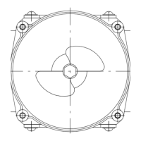
Provides a detailed technical drawing of the product with dimensions and component labels.
Lists essential technical specifications like motor type, voltage, frequency, speed, and power.
Presents energy efficiency data according to EU regulations for fans.
Details technical aspects such as weight, size, materials, and operating characteristics.
Specifies requirements for mounting, including screw strength class and fastening.
Outlines temperature limits for motor transport and storage.
Details EMC immunity and emission standards applicable to the device.
Provides instructions and warnings for physically connecting the device, including handling the packaging.
Details crucial safety warnings and requirements for electrical hookup, including protective earth.
Specifies requirements for electrical connection, including nameplate data, voltage matching, and cable sizing.
Provides a table for assigning supply cable cross-sections and required fuses for different voltage ratings.
Explains reactive currents measured in the supply line due to the EMC filter.
Recommends specific types of RCCBs for use with the device to prevent nuisance tripping.
Mentions the potential increase in leakage current under certain power system conditions.
States that the starting current (LRA) is equal to or less than the nominal current (FLA) due to protection.
Details how to connect wires within the device's terminal box.
Provides instructions on stripping cable lengths and ensuring proper cable gland sealing.
Gives step-by-step instructions for connecting wires to the terminals inside the box.
Offers advice on routing cables to prevent moisture penetration and damage.
Lists the default factory settings for various device parameters like mode and PWM control.
Presents a detailed wiring diagram showing terminal designations and functions.
Outlines essential checks to ensure proper and safe electrical connections before operation.
Provides instructions and warnings for safely powering on and starting the device.
Explains the correct procedures for switching the device off during operation and for maintenance.
Lists specific fault conditions that trigger integrated protective functions and their descriptions.
Describes the protective function for rotor position errors and automatic restart.
Details the protective function for blocked rotors and automatic restart after blockage removal.
Explains protective actions for line undervoltage and phase failure, including automatic restart.
Reiterates the danger of electric shock from live terminals even when the device is switched off.
Warns that the motor may restart automatically after a power failure.
Lists potential malfunctions, their causes, and remedies for troubleshooting.
Addresses issues with the impeller not running smoothly, including imbalance and cleaning.
Covers causes for the motor not turning, such as mechanical blockage or line voltage faults.
Explains issues related to deficient cooling and how to reset error messages.
Discusses the effects of high ambient temperatures and how to reset error messages.
Addresses operation at impermissible points, like high back pressure, and how to reset errors.
Provides guidance on cleaning the fan to ensure long service life and proper operation.
Warns about the severe risk of injury from rotating fans during cleaning.
Provides notes on avoiding damage to the device during cleaning procedures.
Advises on performing high-voltage tests using DC voltage due to EMC filter capacitors.
A table outlining safety inspection items, methods, frequency, and required actions.
Details inspection of contact protection covers for damage.
Specifies visual inspection for damage to blades and housing.
Covers inspection of cable fastening and retightening if necessary.
Details inspection of cable insulation for damage.
Covers inspection of cable gland tightness and retightening or replacement.
Details inspection of condensation drainage holes for clogging.
Covers inspection of welds for crack formation.
Details inspection for abnormal bearing noise.
Emphasizes adherence to applicable country-specific legal regulations for product disposal.
Provides instructions for product disassembly by qualified personnel, warning of heavy parts.
Lists components and their materials for proper recycling, including magnets and electronic scrap.
This document outlines the operating instructions for a device, emphasizing safety, proper usage, and maintenance to ensure optimal performance and longevity.
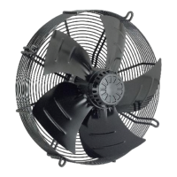
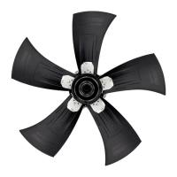
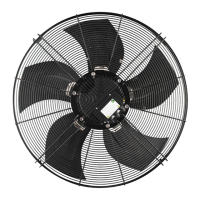
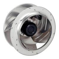
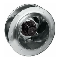
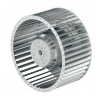
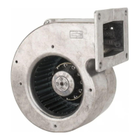
The device is designed for air movement, specifically for ventilation and cooling applications. It incorporates an external rotor motor, which is a compact and efficient design where the rotor is on the outside of the stator. This design allows for a direct drive, eliminating the need for belts and pulleys, thus reducing mechanical losses and noise. The device is equipped with a fan impeller, which is responsible for generating the airflow. The fan operates by drawing air in from one side and expelling it from the other, creating a directed air stream. The motor is designed to operate within specific voltage and frequency ranges, ensuring stable and reliable performance. It also includes protective features to prevent damage from overcurrent, overvoltage, and overheating. The device can be integrated into various systems and controlled through different interfaces, allowing for flexible application in diverse environments. Its robust construction and integrated electronics ensure a long service life and consistent operation.
The device is intended for professional use and must be installed and operated by qualified personnel. Before installation, it is crucial to inspect the device for any damage and ensure that all components are intact. The installation process involves mounting the device securely and connecting it to the electrical supply according to the provided wiring diagrams. Proper grounding is essential to prevent electrical shock. The device can be configured for different airflow directions, depending on the specific application requirements. It supports various control methods, including analog and digital inputs, allowing for precise regulation of fan speed and performance. The device is designed to operate in a wide range of ambient temperatures, making it suitable for diverse environmental conditions. It is important to ensure adequate clearance around the device to allow for proper airflow and prevent overheating. The device is also designed to minimize noise and vibration during operation, contributing to a more comfortable working environment. The integrated protective features, such as thermal overload protection and locked-rotor protection, enhance the device's reliability and prevent damage from abnormal operating conditions. Regular checks of the electrical connections and mounting integrity are recommended to ensure continued safe operation. The device is designed for continuous operation, but it is important to adhere to the specified operating limits to prevent premature wear or failure.
Regular maintenance is crucial for ensuring the long-term reliability and performance of the device. Before any maintenance work, the device must be disconnected from the power supply to prevent electrical shock. The primary maintenance tasks include cleaning the impeller and housing to prevent the accumulation of dirt and dust, which can reduce airflow and efficiency. The fan blades should be inspected for any damage or imbalance, as these can lead to increased vibration and noise. The electrical connections should be checked for tightness and corrosion, and any loose connections should be secured. The device's bearings are designed for a long service life and are typically maintenance-free, but unusual noises or vibrations may indicate a need for inspection or replacement. The protective grille should also be cleaned regularly to ensure unobstructed airflow. Any signs of wear or damage to the cables or housing should be addressed promptly. The device's integrated electronics are designed to be robust, but it is important to protect them from moisture and extreme temperatures. In case of a malfunction, troubleshooting steps outlined in the manual should be followed. If the issue cannot be resolved, the device should be serviced by qualified personnel. The device is designed with replaceable components, allowing for easier repairs and extending its overall lifespan. Proper documentation of maintenance activities is recommended to track the device's history and ensure timely interventions. Adhering to the recommended maintenance schedule will help prevent unexpected breakdowns and ensure the device operates efficiently throughout its service life.
| Model | A3G500-BD59-01 |
|---|---|
| Category | Fan |
| Manufacturer | ebm-papst |
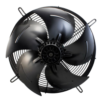
| Type | Axial Fan |
| Housing Material | Plastic |
| Blade Material | Plastic |
| Protection Class | IP54 |
| Speed | 2700 rpm |
| Operating Temperature | -25 to +60 °C |