Do you have a question about the ebm-papst VBS0630STTPS and is the answer not in the manual?
Explains hazard symbols and their meaning for warnings.
Specifies required qualifications for personnel handling the device.
Outlines fundamental safety guidelines for working with the device.
Discusses electrical voltage hazards and safety precautions.
Details integrated safety and protective features of the device.
Addresses potential electromagnetic interference and shielding requirements.
Covers hazards related to the rotating parts of the device.
Mentions potential noise emissions and required precautions.
Warns about hot surfaces and the risk of burns.
Provides guidelines for safe transportation of the device.
Gives instructions for proper storage of the device to maintain condition.
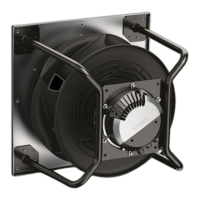
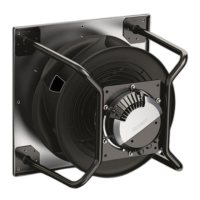
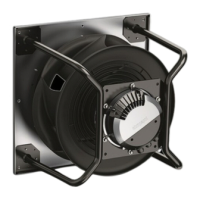
Illustrates the device with dimensions and component references for identification.
Lists essential technical specifications and ratings of the device for performance.
Provides energy efficiency data as per EU regulation for compliance.
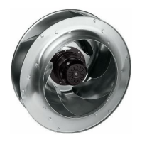
Offers detailed description of the device's technical features and construction.
Guides on physically installing and connecting the device securely.
Details the procedures and safety for electrical hookup.
Lists prerequisites and checks before electrical connection.
Specifies cable sizes, fuses, and voltage ranges for supply connection.
Explains reactive currents due to EMC filters in the supply line.
Advises on the use and types of residual current devices for safety.
Briefly mentions leakage current behavior in specific system conditions.
Describes the device's built-in protection against locked rotor conditions.
Provides instructions for wiring inside the device's terminal box.
Guides on preparing cables and stripping lengths for termination.
Lists cable types, cross-sections, and ferrules for terminals.
Details the process of connecting wires to the correct terminals.
Advises on proper routing of cables to prevent moisture ingress.
Presents a visual representation of the electrical connections for clarity.
Outlines various settings and configurable options for device operation.
Provides steps for verifying electrical connections after installation.
Details the procedure for safely powering up the device.
Explains how to properly shut down the device.
Discusses managing speed ranges with excessive vibration.
Explains the LED status codes for warnings and errors.
Details the meanings of orange LED flash codes indicating warnings.
Lists red LED flash codes indicating errors and their resolutions.
Describes how to perform manual vibration tests on the fan.
Provides instructions for cleaning the device safely.
Outlines regular safety checks and their frequency.
Gives recommendations for environmentally friendly disposal.
Mentions compliance with local disposal regulations.
Provides guidance on safely disassembling the product for disposal.
Lists categories of components for recycling and disposal.
This document describes the ebm-papst VBS0630STTPS device, an axial fan designed for air conveyance. It serves as a comprehensive guide for safe and effective installation, operation, and maintenance.
The VBS0630STTPS is a built-in device specifically engineered for conveying air according to its technical specifications. It operates within power systems with grounded neutral (TN/TT), phase conductor grounding, or IT power systems, adhering to EN 50160 network quality characteristics. The device is intended for stationary systems and performs all necessary maintenance work. It conveys air at ambient air pressures between 800 mbar and 1050 mbar, within a permitted ambient temperature range. The fan is designed to operate with all protective devices in place and requires adherence to its operating instructions.
Improper use, which is prohibited and potentially hazardous, includes operating the device in an unbalanced state (e.g., due to dirt or ice formation), in resonant operation with severe vibration, or in medical equipment with life-sustaining functions. Conveying solids, abrasive particles, or highly corrosive air (unless specifically designed for it), operating in explosive atmospheres, or using it as a safety component are also forbidden. The device should not be painted, and connections must remain secure during operation.
The device features an operation and alarm display with an LED. It includes an external 15-50 VDC input for parameterization, an alarm relay, an integrated PI controller, configurable inputs/outputs (I/O), and MODBUS V6.4. Other features include motor current limitation, active PFC, RS-485 MODBUS-RTU, soft start, and a voltage output (3.3-24 VDC, Pmax = 800 mW) for external devices. The control interface utilizes SELV potential safely disconnected from the mains. Thermal overload protection for electronics/motor, line undervoltage/phase failure detection, and a vibration sensor are also integrated.
For electrical connection, supply cable cross-sections and required fuses are specified (e.g., 3/PE AC 380-480 VAC: 16A fuse for 1.5 mm² cable, 20A fuse for 2.5 mm² cable, 25A fuse for 4.0 mm² cable). Reactive currents, typically less than 500 mA, can be measured in the supply line even when the motor is at a standstill due to the integrated EMC filter. If a residual current device (RCD) is required, only AC/DC-sensitive devices (type B or B+) are permissible, with a recommended trip threshold of 300 mA and delayed tripping (super-resistant, characteristic K).
The device has locked-rotor protection, ensuring the starting current (LRA) is less than or equal to the nominal current (FLA). Cables should be prepared by stripping only as much as necessary to ensure a sealed cable gland and no strain on connections. The terminal box includes partitions to aid in separate routing of supply and control cables. The protective earth "PE" must be connected first, with a tightening torque of 3.5 ±0.4 Nm. Cables should be routed to prevent water ingress into the terminal box, ideally in a U-shaped loop.
The device should only be switched on after proper installation, adherence to intended use, and verification of safety mechanisms and electrical hookup. It is crucial to ensure no combustible or flammable materials are near the fan and that protective devices are functional. The fan's airflow paths should be clear of foreign matter.
The device is equipped with integrated protective functions that automatically switch off the motor in case of faults such as rotor position detection error, blocked rotor, line undervoltage, or phase failure. These faults trigger specific safety responses, including automatic restarts once the issue is resolved.
Regular safety inspections are recommended, including checking the contact protection cover, blades, housing, cable fastenings, protective earth terminal, cable insulation, impeller for wear/deposits/corrosion, cable gland tightness, and condensation drainage holes. A visual inspection should be performed at least every 6 months, with repairs or replacements as needed. Abnormal bearing noise and vibration should be addressed promptly.
For vibration testing, if the integrated sensor is not used, a "manual" vibration test must be performed every 6 months across the fan's entire speed range. Speed ranges with excessive vibration velocities should be avoided or quickly passed through. The fan is equipped with maintenance-free ball bearings designed for a service life of 40,000 hours.
Cleaning is essential for a long service life. Fans should be checked regularly for soiling, with cleaning frequency adjusted based on the degree of soiling. Cleaning should only occur when the fan is not in motion and disconnected from the power supply. Dry cleaning, such as with compressed air, is the preferred method. Aggressive cleaning agents, high-pressure cleaners, acids, alkalis, solvents, or sharp objects should not be used. After cleaning, the fan should be operated for 2 hours at maximum speed to evaporate any water. If cleaning does not eliminate vibrations, the fan may need rebalancing.
For disposal, ebm-papst prioritizes environmental protection. The product components, primarily steel, copper, aluminum, and plastic, should be separated for recycling. Metallic materials are fully recyclable. Ferrite magnets, used in external rotor motors, can be disposed of with normal iron and steel. Electrical insulating materials should be treated similarly. Electronic components should be disposed of according to proper electronic scrap procedures.