Chengdu Ebyte Electronic Technology Co.,Ltd. E95-DTU(900SLxx-485) User Manual
Copyright ©2012–2022,Chengdu Ebyte Electronic Technology Co.,Ltd.
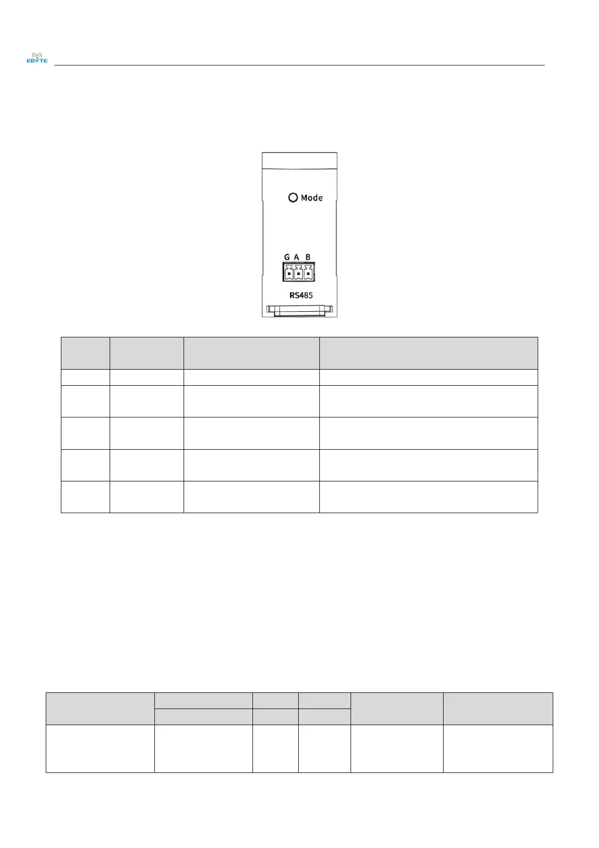
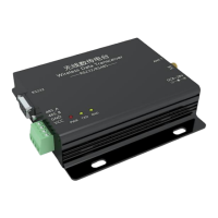
2.2 Communication interface description
The E95-DTU (900SLxx-485) can be connected to the device through RS485 using the terminal block.
Anti-interference, grounding
The RS485 interface A interface is connected to
the device A interface
RS485 interface B interface is connected to
device B interface
The RS232 interface TX interface is connected
to the device RX interface
The RS232 interface RX interface is connected
to the device TX interface
Note: When the radio is connected with multiple devices, the communication is not smooth, but there is no such
phenomenon when a single device is connected. Please try to connect a 120Ω resistor in parallel between the
485_A terminal and the 485_B terminal.
3.Technical indicators
3.1 Model Specifications
Recommended
application scenarios
New generation
LoRa spread
spectrum, DC
long-distance,
interference-prone
environments.