Do you have a question about the Echo IG3500E and is the answer not in the manual?
Explains the importance of the operator's manual for safe operation and troubleshooting.
Explains the safety alert symbol and signal words used in the manual.
Defines common hazard symbols like explosion, fire, electric shock, etc.
Provides essential safety guidelines for generator operation, including indoor use, fuel handling, and electrical safety.
Details safe procedures for connecting the generator to a home power supply, emphasizing qualified electricians and proper wiring.
Describes various warning labels and symbols found on the generator for safe operation.
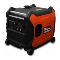
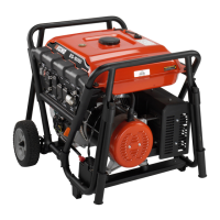
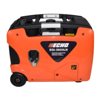
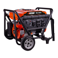
Identifies and labels the main parts of the generator unit.
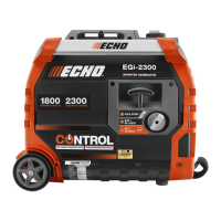
Identifies and labels the components on the generator's control panel.
Explains the operation of the 3-in-1 switch (OFF, CHOKE, ON) for starting and running the engine.
Describes the function of the Engine Smart Control (ESC) for economy and noise reduction.
Explains the digital display meter for normal operation and fault indicators like over/under voltage.
Details the function of the oil warning light and its relation to engine shutdown and oil level.
Explains the overload indicator light, its causes, and troubleshooting steps when it activates.
Describes the AC pilot light, indicating when the engine is producing power.
Explains the DC protector's function in preventing overload and how to reset it.
Describes the ground terminal's purpose for preventing electric shock.
Explains the purpose of parallel operation outlets for connecting two generators.
Describes the function of the brake for securing the generator during operation or idle.
Emphasizes the necessity of pre-operation checks before each use.
Provides critical warnings and instructions for safe fuel handling and filling.
Details the procedure for filling engine oil, as the generator is shipped without it.
Step-by-step guide on how to start the generator engine, including ESC and choke settings.
Instructions for using the electric start feature, including battery care.
Instructions for using the recoil start method, including safety tips.
Explains the procedure for stopping the generator engine safely.
Provides warnings and procedures for connecting electrical devices to the AC receptacles.
Step-by-step instructions for charging a 12V battery using the generator.
Details how to connect two generators for parallel operation to increase power output.
Discusses tips and warnings for using the generator in parallel operation, including load management.
Outlines the AC and DC output capabilities and recommended usage wattage for the generator.
Important notices regarding overloading, electrical interference, and specific equipment compatibility.
A schedule detailing routine maintenance tasks and their frequency (pre-operation, 6/12 months).
Continues the maintenance schedule, covering items like crankcase breather hose and valve clearance.
Step-by-step guide on how to inspect, clean, and gap the spark plug.
Advises leaving carburetor adjustment to a qualified dealer due to complexity.
Instructions for removing, cleaning, and reinstalling the fuel filter.
Detailed steps for draining and refilling the engine oil, with safety precautions.
Guide for cleaning and oiling the air filter for optimal engine performance.
Instructions for cleaning the muffler screen to prevent performance issues.
Covers cleaning the muffler screen and checking/replacing the spark arrester.
Procedures for draining fuel for long-term storage to prevent deterioration.
Steps to protect the engine from corrosion during storage, including oiling cylinder walls.
Lists common causes and solutions for the engine failing to start.
Troubleshooting steps for when the generator is not producing power.
Technical specifications for the IG3500E generator, including electrical and engine data.
Detailed engine specifications such as type, displacement, fuel, and oil capacity.
Physical specifications of the generator set, including dimensions and weight.
Illustrates the electrical connections and components of the generator's wiring system.
| Displacement | 212 cc |
|---|---|
| Max Output | 3500 watts |
| Rated Output | 3000 watts |
| Fuel Tank Capacity | 4 gallons |
| Fuel Type | Gasoline |
| Rated AC Voltage | 120V |
| Frequency | 60 Hz |
| Engine Type | 4-stroke, single cylinder |
| Starting System | Recoil |
| Noise Level | 68 dB at 23 feet |