10
D
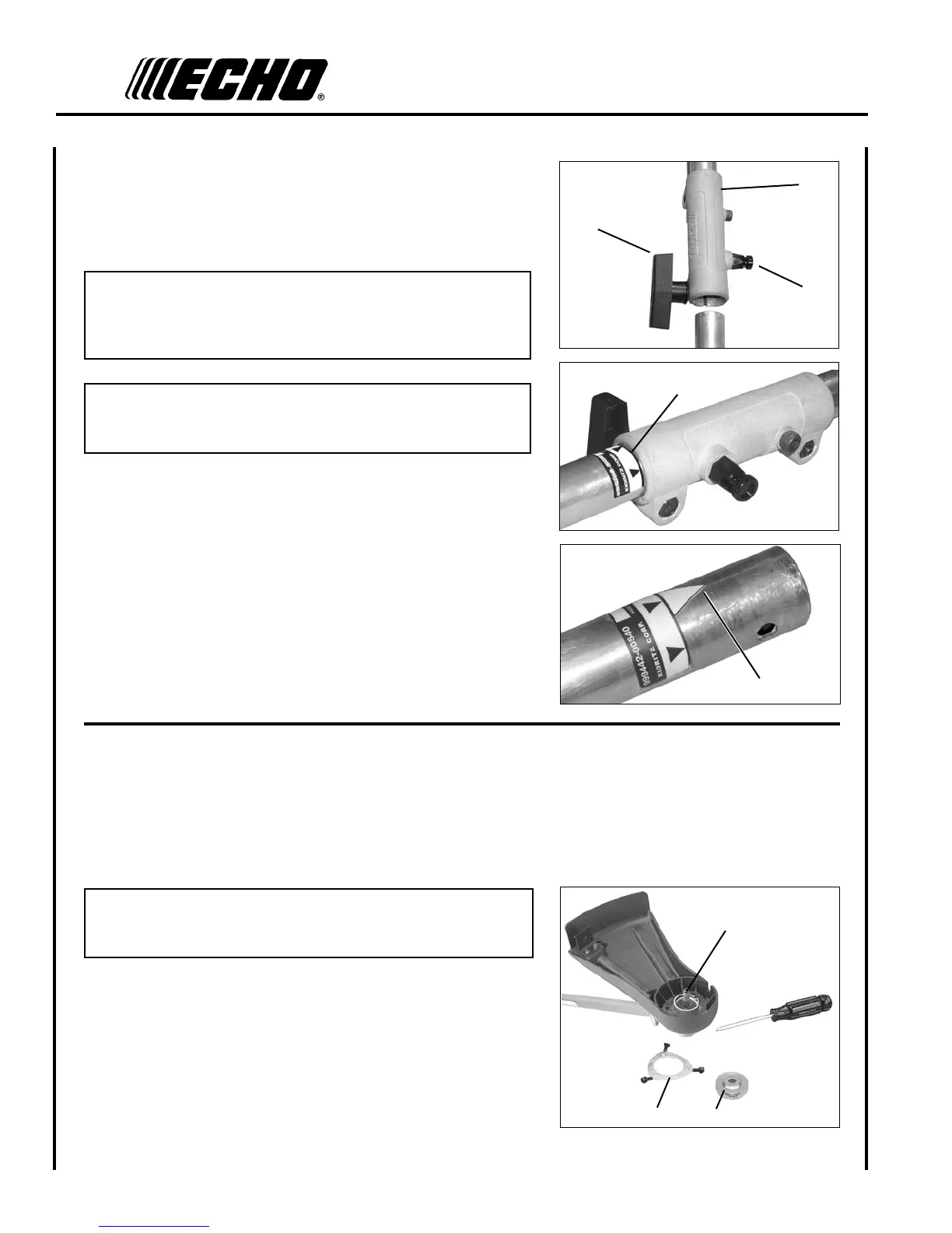
A
C
B
E
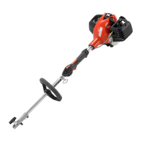
5. Carefully t attachment drive shaft assembly into coupler (B) to
decal assembly line (C), making sure that the inner lower drive shaft
engages the square upper drive shaft socket.
NOTE
Earlier model Power Heads may have shorter couplings. Short
couplings t ush to decal point (E). New couplings are 4-3/4 in.
long, and t ush to line (C).
NOTE
Lower bearing housing and head assembly must be in line with the
engine.
6. Rotate locator pin (A) 1/4 turn clockwise to engage lower shaft
hole. Insure locator pin is fully engaged by twisting lower drive
shaft. Locator pin should snap ush in coupler. Full engagement
will prevent further shaft rotation.
7. Secure lower shaft assembly to coupler by tightening clamping
knob (D).
p l a s t I c s h I e l d I n s t a l l a t I o n
(for Nylon Line Operation)
Tools Required: Torx T27 L-Wrench
Parts Required: Plastic Shield, Shield Plate, three (3) 5mm x 16mm
screws.
NOTE
The plastic shield is for use with the Nylon Line Head only.
Install Metal Shield when using plastic or metal blades.
1. Remove plastic threaded shaft sleeve and adapter plate (C) from
PTO shaft (A).
2. Place the shield on the bottom of the bearing housing ange.
3. Place shield plate (B) on shield, align holes. Install three (3) screws
from bottom through plate and shield into gear case.
4. Assemble adapter plate (C) onto PTO shaft.
A
B
C