P
OWER
P
RUNER
TM
O
PERATOR
'
S
M
ANUAL
15
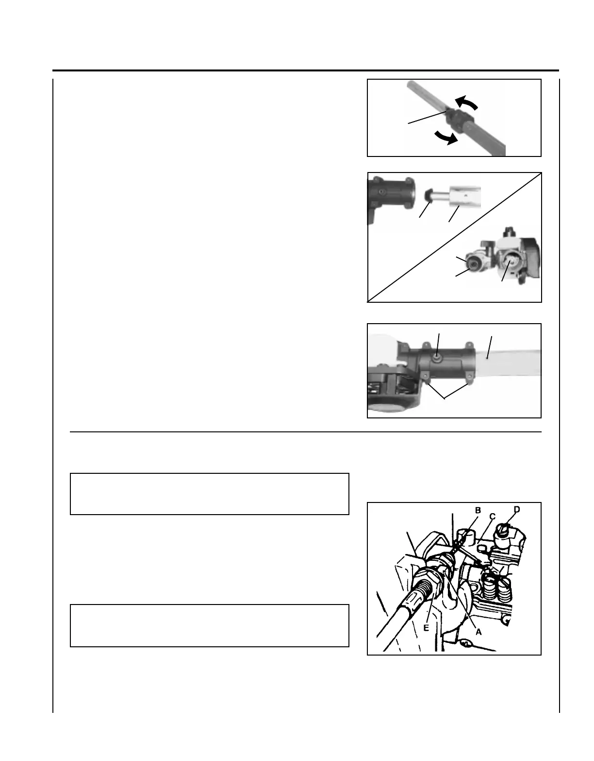
2. Loosen center clamp knob (F) turning counter clockwise.
3. Pull upper shaft tube (G) out of fiberglass lower shaft tube 127-152
mm (5-6 in.), then slide (G) back into fiberglass lower shaft tube
exposing inner power transmission shaft (H). Align and join star
shaped drive end of inner power transmission shaft (H) with cutting
attachment shaft (I).
4. Align ridges on upper shaft tube (G) with seams in cutting attach-
ment.
5. Slide together aligning locator screw (E) in cutting attachment with
locating hole (J) in upper shaft tube.
6. Tighten locator screw (E). Tighten four (4) cutting attachment
screws (D).
7. Extend upper shaft tube to desired length. Tighten center clamp
knob (F) turning clockwise.
E
THROTTLE LINKAGE INSTALLATION
D
F
NOTE
The engine is delivered separated from shaft tube. The throttle
linkage and stop switch wires are attached to the rear handle.
1. Loosen outer 10mm nut (E) on throttle linkage.
2. Insert throttle linkage in fan cover slot (A).
3. Finger tighten nut (E) and attach the inner linkage to the swivel (B)
on the carburetor throttle plate.
NOTE
It is important that the head of the throttle linkage fits inside the
slot well of the swivel (B).
G
H
G
H
I
J
 Loading...