43
SRM-360SL
E
N
G
L
I
S
H
D
E
U
T
S
C
H
I
T
A
L
I
A
N
O
1
2
3
4
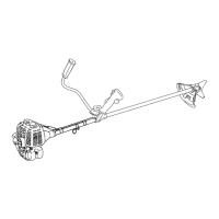
1. Right hand U-handle
2. Wire fixing clip
3. Shaft tube
4. Throttle wire
1. Rechter Handgriff
2. Kabelklemme
3. Kabelhülle
4. Gaszug
1. Impugnatura destra ad U
2. Fermo cavo acceleratore
3. Tubo albero trasmissione
4. Cavo acceleratore
To eliminate loosening of throttle wire fix it to shaft tube
(2 places) and to right hand U-handle (1 place) with wire
fixing clips.
Um zu verhindern, daß sich der Gaszug löst, fixieren Sie
ihn am Schaft mit 2 Kabelklemmen und am rechten Griff
mit einer Kabelklemme, wie nebenstehend abgebildet.
Per evitare I’allentamento del cavo acceleratore fissatelo
al tubo dell’albero (2 posizioni) e all’impugnatura destra ad
U (1 posizione) con i fermi di fissaggio.
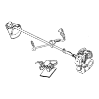
INSTALLATION OF BRACKET
Fit bracket to mounting portion of angle transmission and
fix the bracket by holding fitting plate pressed from beneath
and tightening 4 bolts (M5×25) lightly.
Get notches and convexes of fitting plate to face
corresponding convexes and concaves of bracket, and fix
bracket tightening 4 bolts (M5×25) securely.
3
4
5
1
2
1. Bracket
2. Bolt M5×25
3. Convex of fitting plate
1. Supporto
2. Bullone M5×25
3. Convesso della piastra
di raccordo
MONTAGGIO DEL SUPPORTO
Adattate il supporto alla parte di montaggio della testina e
fissate il supporto tenendo la piastra di raccordo premuta
verso il basso e stringendo le 4 bulloni (M5×25), ma non
troppo.
Fate combaciare gili incavi e i convessi della piastra di
raccordo in modo che convessi e concavi del supporto
coprispondano e fissate il supporto stringendo bene le 4
bulloni (M5×25).
ZUSAMMENBAU DER RUNGE
Befestigen Sie die Runge am Winkelgetriebe indem Sie
die Befestigungsplatte von unten dagegen drücken und
die 4 Schrauben (M5×25) leicht anziehen.
Bringen Sie die Kerbe und den Fixierpunkt der
Befestigungsplatte auf das entsprechende Gegenstück
der Runge und ziehen Sie die 4 Schrauben (M5×25) fest.
4. Fitting plate
5. Notch of fitting plate
4. Piastra di raccordo
5. Incavo della piastra di
raccordo
1. Runge
2. Schraube M5×25
3. Fixierungspunkt in der
Befestigungsplatte
4. Befestigungsplatte
5. Kerbe in der
Befestigungsplatte