Stand-Alone Operation
Measurement and the SYS Key
Upon power-up, the AFRecorder executes the following sequence:
1. System initialization is performed. The displays show "Initializing" and the
internal buzzer is tested.
2. If the AFR measurement function is enabled (see AFR Measurement
Enable/Disable on page 23), the left display begins a 40 second countdown to
allow the AFR sensors to reach operating temperature. If the "SYS" key is
pressed during the countdown, the main menu is displayed.
During countdown, the right display shows the sensors' status (i.e. enabled or dis-
abled) and programmed AFR offsets (see AFR Measurement Offsets, page 22).
3. After the countdown has completed, the AFRecorder begins the measurement
and display of Air-to-Fuel Ratio (AFR), Average Deviation of AFR (DEV), Left
minus Right Sensor AFR (L-R), and Average AFR of both sensors (AVG). The
left AFR sensor's values are displayed on the left display and the right AFR
sensor's values are displayed on the right display. Depending on prior
programming (see Setup - Display on page 17), the AFRecorder may enlarge
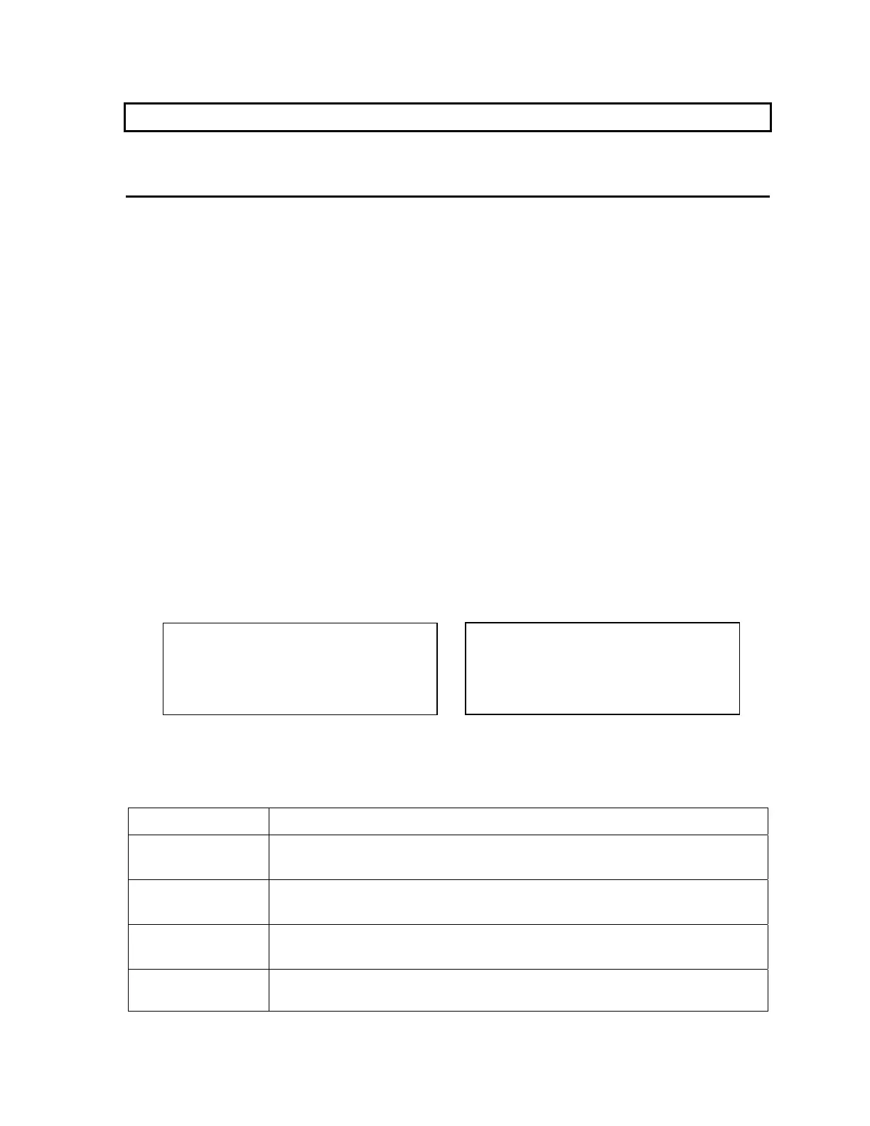
one of these parameters on each display. Figure 1 shows the AFRecorder's
displays during measurement.
Figure 1: AFRecorder Displays During Measurement
Information other than the measured AFR is shown depending on certain conditions:
Display Meaning
%O2: 20.7
AFR measurement function properly calibrated in air.
See AFR Measurement Calibration ("AIR CAL") on page 22.
xxxx
AFR measurement function error.
See Troubleshooting on page 43.
V LO
Supply voltage to AFRecorder is less than 11 VDC (4800P)
or AFR sensor is disconnected.
OFF
AFR measurement function disabled.
See AFR Measurement Enable/Disable on page 23.
AFR: 17.50
DEV: 0.79
L-R: 0.12
AVG: 17.56
AFR: 17.62
DEV: 0.82
L-R: 0.12
AVG: 17.56
Stand-Alone Operation 11