100/157
SDi Decades Extreme Service Manual www.ecoer.com
May. 2023Manufacturer reserves the right to change specifications or designs without notice.
Index:
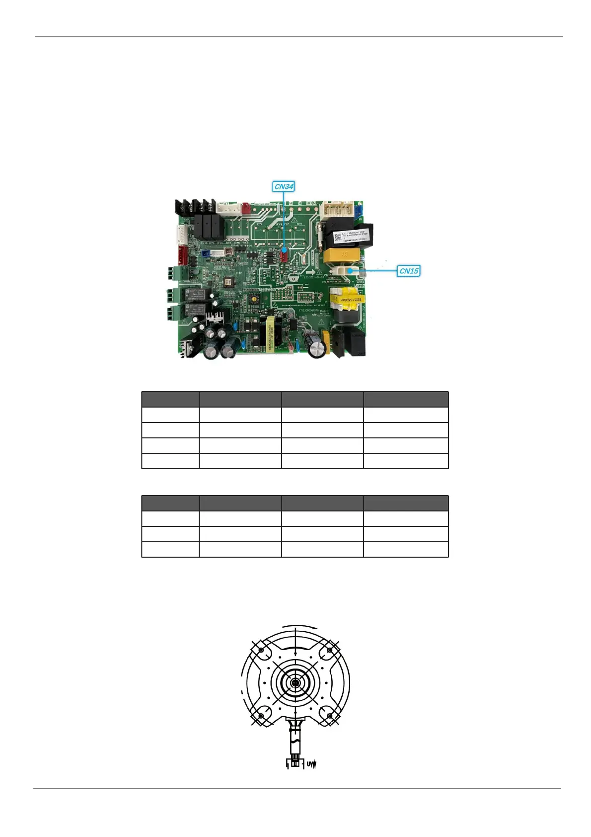
1. Indoor DC Fan Motor(control chip is in fan motor)
Power on and when the unit is in standby, measure the voltage of pin1&pin2 of CN15, pin3 of CN34 in fan
motor connector. If the value of the voltage is not in the range showing in below table, the PCB must has
problems and need to be replaced.
CN34
CN15
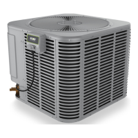
2. Outdoor DC Fan Motor (control chip is in outdoor PCB)
Release the UVW connector. Measure the resistance of U-V, U-W, V-W. If the resistance is not equal to each
other, the fan motor must has problems and need to be replaced. otherwise the PCB must has problems and
need to be replaced.