45/157
SDi Decades Extreme Service Manual www.ecoer.com
May. 2023Manufacturer reserves the right to change specifications or designs without notice.
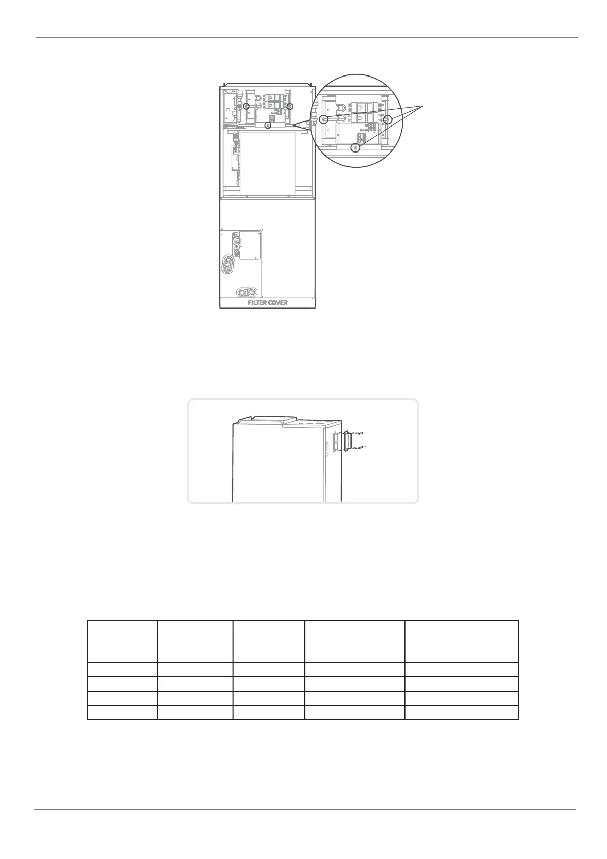
4. Tighten the mounting screws.
5. Wiring according to the wiring nameplate.
6.Tape the wiring diagram to the inside cover wiring is completed for future reference and maintenance.
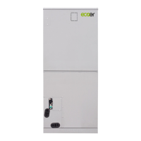
7. Install the upper cover.
8. Install circuit breaker cover.
screws
After the electric heating wiring is connected, please confirm before power on:
• Check all wiring and ensure reliable connection of wire body.
• Check the electric heating fixing screw, and the screw is fixed reliably.
• The size selection of power wire meets the power supply requirements.
9. After installing the electric auxiliary heat module, apply the circuit breaker label near the silicone breaker cover
that was just applied.
Number of
circuit breakers
Number of power
cord groups
Number of power
cord grouding screws
NOTE:
• Electric auxiliary heating wiring diagram packed with the accessories.
• If branch circuit wire length exceeds 100 ft, consult NEC 210-19a to determine maximum wire length. Use
2 % voltage drop.