6
To remove the tube from this type of fitting, first pull or push
the gray collar towards the fitting body, then pull out the
tube.
4.3 Pump Shelf with Pump
1. The shelf may be directly mounted on a wall using the
supplied wall mount anchors and screws. For multiple
pump mountings, the Multiple Pump Mounting Bracket
may be used.
Refer to Section 3, page 4
.
2. Mount the shelf so the pump inlet is a maximum of 3-1/2
ft. (107 cm) above the drums lowest possible liquid level
and 10 ft. (3 meters) maximum horizontal. Always locate
the pump above the product drum.
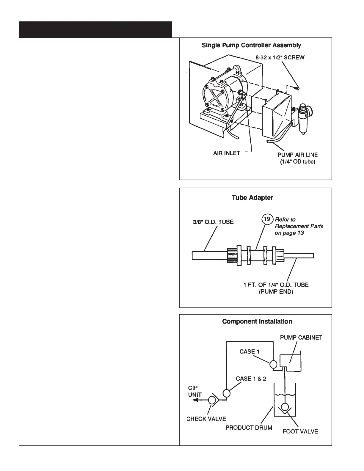
3. Take the free end of the "Pump Air Line" coming from the
pneumatic cabinet and insert it approximately 1/2 inch into
the fitting on the side of the pump. It will be automatically
retained. Make a reference mark 1/2" from the tube and
prior to the insertion
To remove the tube from this type of fitting, first pull or push
the gray collar towards the fitting body, then pull out the
tube
4. If a 3/8" OD pump air line is required (
See Section 4.1 #2
on page 5
), it may be adapted to the pump fitting as
illustrated.
Refer to Figure 9.
5. For product lines, use 19/32" OD x 3/8 ID EVA reinforced
tubing for the discharge line. Install this line to the top
pump port.
6. Install 1/2" OD x 3/8" ID polyethylene or EVA (unreinforced)
tubing for the intake line. The unreinforced EVA tubing is
preferred because of its flexibility. Install this line to the
bottom pump port.
7. Install on the intake line a foot valve.
Refer to Section 4.5
below.
4.4 Anti-Siphon Valve
Install the anti-siphon valve according to the direction of the
specific installation case. Match anti-siphon valve to product
being dispensed. See replacement parts.
CASE 1 - (injecting into the suction side of the CIP pump and
when the chemical feed pump is above injection point).
1. Place an anti-siphon valve within 2 ft of the chemical feed
pump in its discharge line. Also install a second anti-
siphon valve ahead of the check valve at the injection
point. Condition of this case is based on the pump being
above the product tank.
Refer to Figure 10.
CASE 2 - (Injecting into the suction side of the CIP pump and
when the chemical feed pump is below injection point).
1. Place an anti-siphon valve ahead of the check valve at the
injection point.
Refer to Figure 10.
4.5 Ball Foot Valve
1. The ball foot valve is used along with the drum probe.
4.0 INSTALLATION PROCEDURES (con't)
Figure 8
Figure 9
Figure 10

 Loading...