10
8.0 PERIODIC MAINTENANCE
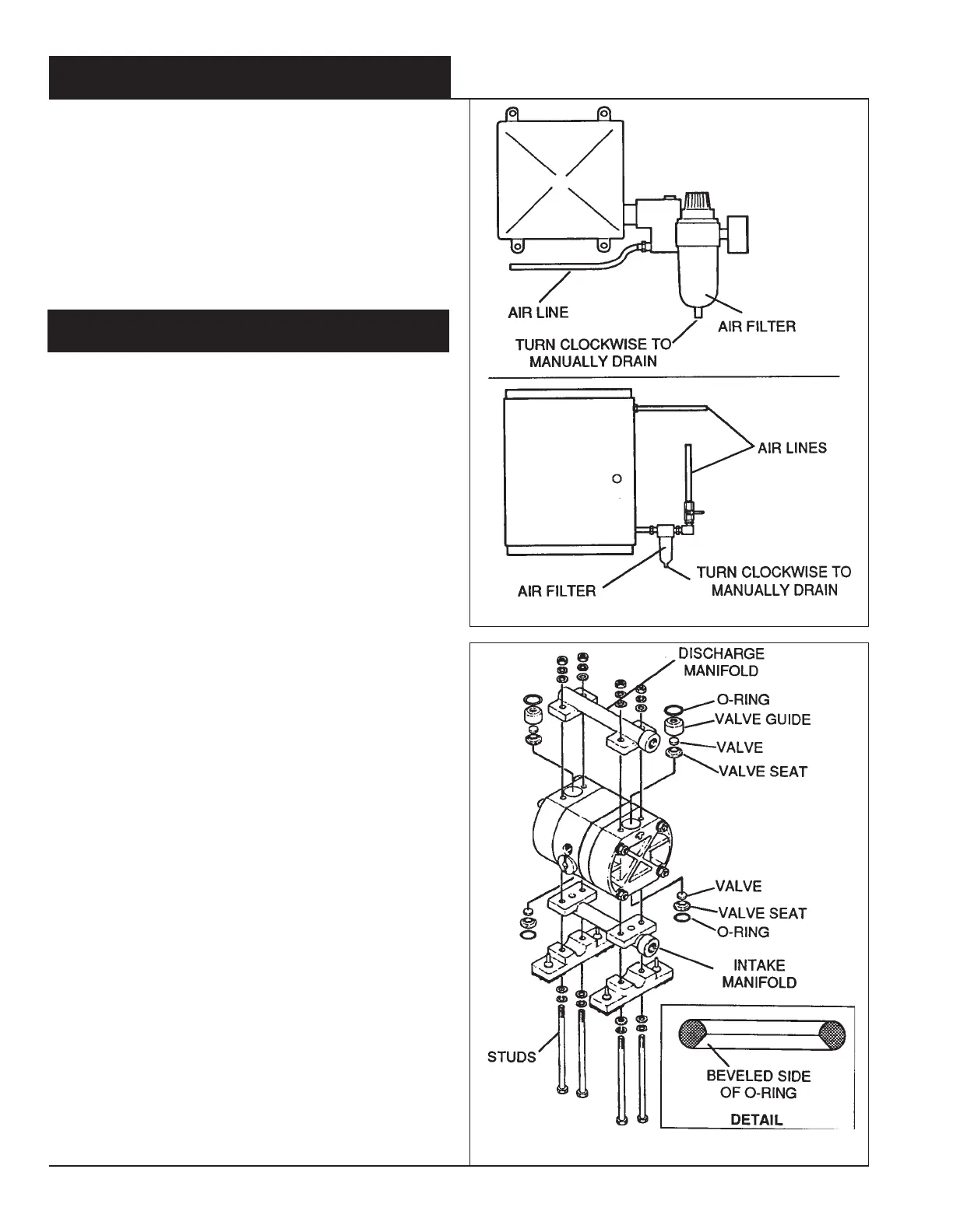
1. Manually drain air filters monthly. These filters have an
automatic drain, but a monthly check should be done.
Annually replace filter element.
Refer to Figure 13.
2. Check day tank(s) for debris.
3. Check exterior of fittings, anti-siphon valves and check
valves for leaks.
4. Check product and air tubing for cracks or damage.
9.0 PUMP SERVICING
WARNING - Wear safety goggles, rubber gloves and other
required protective clothing when removing the pump
from its circuit. Proceed with caution when disconnecting
the discharge line because it may be pressurized. When
disconnecting a discharge line fitting, place a rag over the
fitting to shield yourself from any possible spray.
9.1 Pump Check Valve Servicing
1. For safety reasons, disconnect air line a pump.
See
Section 4, paragraph 4.3, page 6
for method of line
disconnection.
2. Disconnect product discharge line at the CIP unit.
3. Reconnect air line at the pump.
4. Pump water to flush out the product within the pump.
5. Remove pump from shelf.
6. Using two-10mm wrenches, one for each nut at opposite
ends of a vertical stud, remove the nuts and washers from
the four vertical studs.
7. Separate the discharge (top) manifold from the pump.
Remove the o-rings, valve guides, valves and valve seats.
Examine the valves and valve seats for damage or em-
bedded debris.
Refer to Figure 14.
8. Turn the pump upside down and separate the intake
(bottom) manifold. Remove the o-rings, valve seats and
valves. Examine the valve seats and valves for damage or
embedded debris.
HINT - If reusing the o-rings replace with the beveled side
towards the mating part (valve seat or guide).
Refer to
"DETAIL" in Figure 14.
HINT - Before reinstalling the vertical studs, note that the
studs have a shorter thread length on one end as opposed
to the other. Place the nuts and washers on the short end
of the studs before installation.
9. Reassemble the intake side first. Begin by squarely plac-
ing the valve into the pump, lay the valve seat onto the
valve and position the o-ring. Next, install the manifold,
install the mounts and insert the four studs.
10. Holding the intake manifold firmly on the pump, turn the
pump right side up and place it on a work surface.
Figure 13
Figure 14

 Loading...