11
11. Begin assembling the discharge side by installing the
valve seat. Squarely locate the valve onto the seat. While
keeping the valve centered install the valve guide. Install
the o-ring, manifold and secure with washers and nuts.
12. Tighten nuts to 35 to 45 in-lbs.
10.0 INSTALLATION OPTIONS
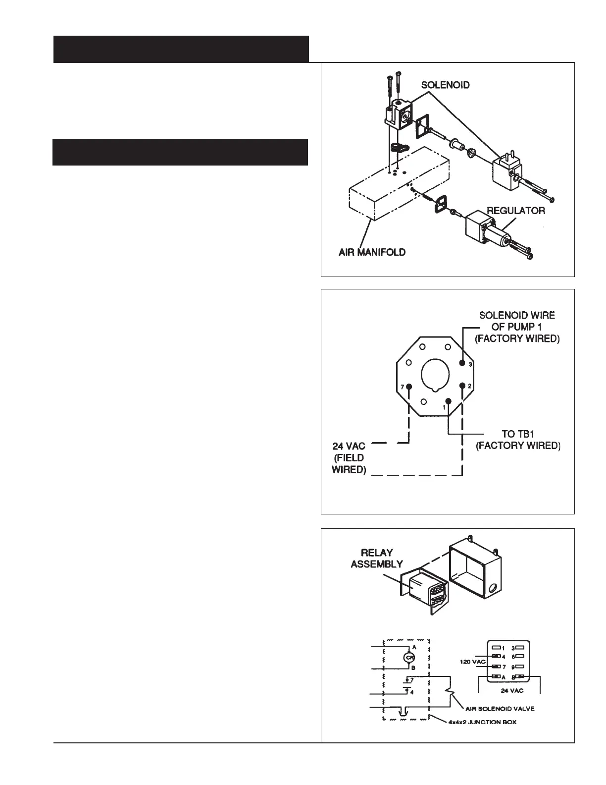
10.1 Adding a Solenoid and Regulator
1. Remove the ty-wraps that are supporting the solenoid
leads inside the control cabinet.
2. Remove the (10) screws on the exterior right side of the
control cabinet that are holding the air manifold mounting
panel to the cabinet. With the manifold attached to the
panel, pull the panel away from the cabinet.
3. To allow mounting a solenoid and regulator, remove the
port covers from the next available manifold station.
4. Mount the solenoid and regulator as shown in
Figure 15
.
Secure their mounting screws firmly.
5. Remount the manifold panel.
6. Attach the solenoid leads to the next available position on
the terminal block.
7. Attach the ty-wrap mount in the cabinet.
8. Individually bundle the solenoid leads and secure them to
a mount with a ty-wrap.
9. Install the pressure gauge by inserting the gauge tube
end, about 1/2 inch, into the mating part on the solenoid
valve.
10.2 S-2000 for Multiple Pump Controller
1. Signal wires from the S-2000 should be connected to
terminals 2 and 7 of the octal socket. Remove from the
socket the purple jumper wire between 1 and 3. Install into
the socket the 24 VAC relay (item 7 "Replacement Parts"
page 13). This will control "Pump 1".
Refer to Figure 16
.
10.3 S-2000 for Single Pump Controller
1. If a 24 VAC signal is used, make an additional hole in the
junction box (7/8 diameter is required for 1/2 electrical
conduit) for the 24 VAC signal. Use the special 24 VAC
relay assembly, (Item 12, "Replacement Parts" on page
13). Slide this assembly into the junction box. R
efer to
Figure 17.
9.0 PUMP SERVICING (con't.)
Figure 15
Figure 16
Figure 17

 Loading...