5
4.1 Multiple Pump Pneumatic Controller
HINT: If this system is replacing a different system, label
any control wires prior to disconnecting that will be recon-
nected to the new system.
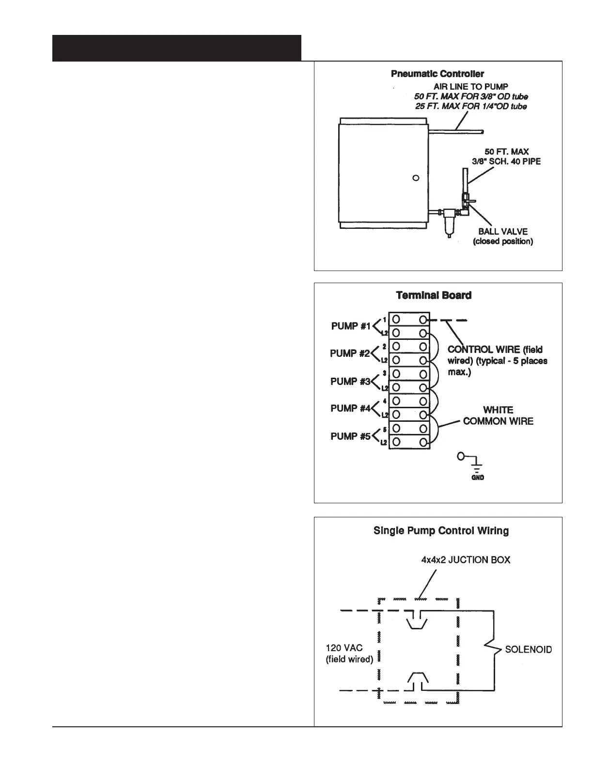
1. Locate a practical place for the Pneumatic Controller so
the air lines from the controller to the pump do not exceed
50 ft (15 meters). Also, consider the relative location of the
compressed air source that will be connected to the
controller's air inlet.
(See item 4).
2. For air lines to pumps, 1/4" O.D. tubing is recommended
for lengths up to 25' and 3/8" O.D. tubing is used for
lengths from 25 to 50 ft.
Refer to Figure 5.
3. Mount the controller using the enclosed wall mount an-
chors and screws.
4. For the main air supply line, due to air supply require-
ments, it is recommended to use 3/8" sch. 40 pipe mini-
mum for a maximum length of 50 ft.
5. Connect supply air line to the ball valve preceding the
5 micron filter. Leave the ball valve closed.
Refer to
Figure 5.
NOTE: Do not use an air lubricator.
6. Turn regulator control knobs full counter clockwise. This
will effectively shut off the air supply to the pump until
regulating to desired pressure.
7. Connect pump air lines to the fittings on the right side of
the controller by wrench tightening the fitting nuts, maxi-
mum of one turn beyond finger tight.
Refer to Figure 5.
8.
Connect 110/120 VAC, 50/60 Hz control wire to the right
side of the 10 point terminal block.
Refer to Figure 6.
NOTE - Remove white common wire harness when
more than one process controller is entering the
pneumatic control cabinet. Use individual neutrals/
commons in place of the harness.
9. Connect a ground wire to the post located to the right of the
terminal strip.
Refer to Figure 6.
4.2 Single Pump Pneumatic Controller
1. Mount the controller to the left side of the pump cabinet
using the four 8-32 x 1/2" screws that are supplied.
Refer
to Figure 8.
2. Bring a 110/120 VAC, 50/60 Hz signal into the bottom of
the junction box and wire nut to the solenoid leads.
Refer
to Figure 7.
3. Connect supply air line to the ball valve preceding the
5 micron filter/regulator. Leave the ball valve closed.
NOTE - Do not use an air lubricator.
4. Turn regulator control knob full counter-clockwise.
5. Install free end of the 1/4 O.D. tubing to the air inlet side
of the pump. The type of fitting on the pump to receive this
tubing requires approximately 1/2 inch insertion of the
tube to be automatically retained. Make a reference mark
1/2" from the tube and prior to the insertion.
Refer to
Figure 8
4.0 INSTALLATION PROCEDURES
Figure 5
Figure 6
Figure 7

 Loading...