8
6.1 Multiple Pump Pneumatic Controller
1. Check that all pump control regulator adjustment knobs
are in the full counter-clockwise position.
2. Check that the pump intake probes are in the appropriate
products.
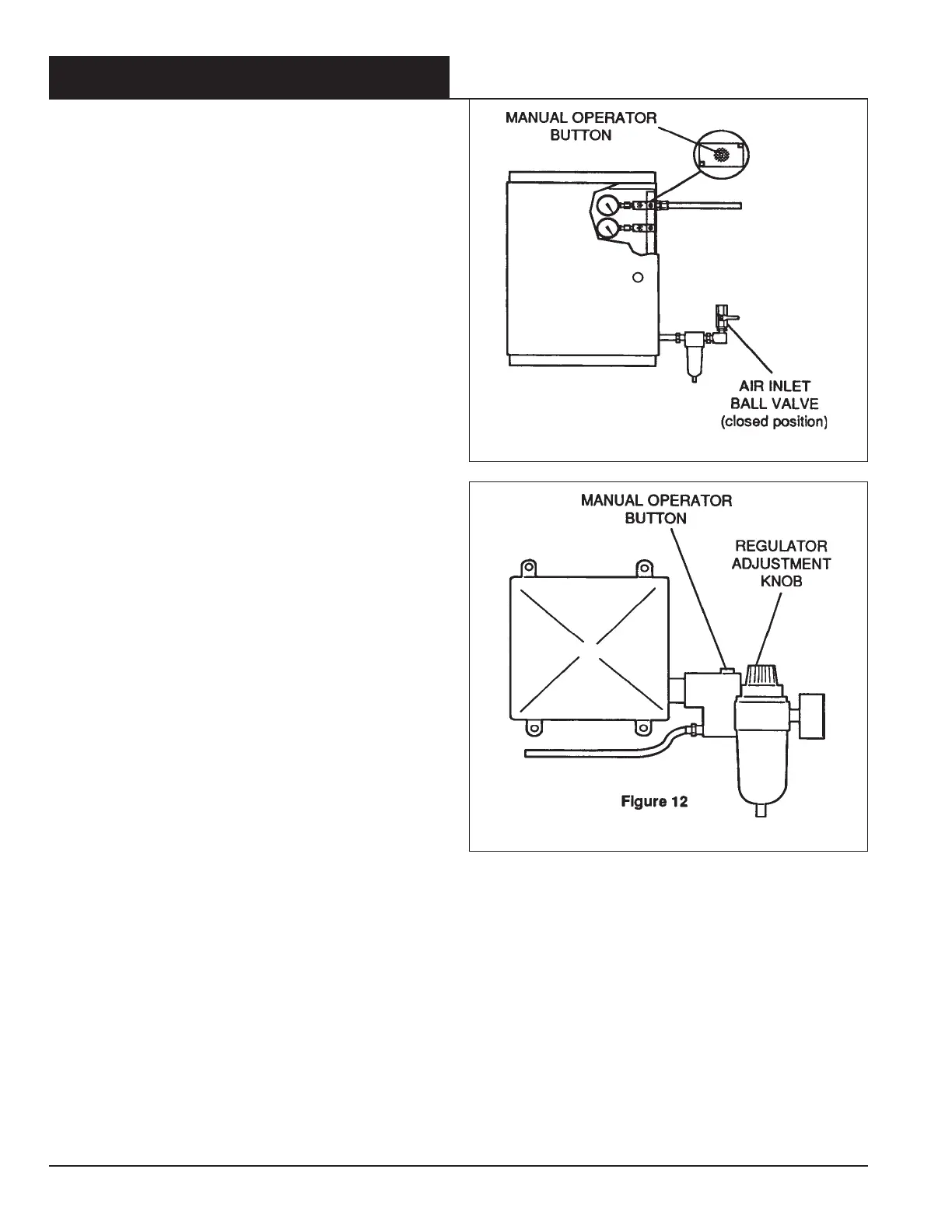
3. Open the air inlet ball valve.
Refer to Figure 11.
4. While pressing the manual operator button on the sole-
noid valve with a "pen tip", rotate the regulator adjustment
knob until the pump starts (approximately 18 psig or 1.2
bars)
5. Continue to increase the air pressure to establish the
pressure needed for the required flow rate.
Refer to the
graphs in Section 11, page 12
to use as a set-up guide line
to determine this approximate air pressure.
6. Fine tune the delivery by taking a solution sample and
titrate it.
7.
Refer to paragraph "6.3 Pump"
below for additional pump
delivery information when less than 20 oz./min.
6.0 OPERATIONS
6.2 Single Pump Pneumatic Controller
1. Check that the regulator control knob is in the full counter-
clockwise position.
2. Check that the pump intake probe is in the product.
3. Open the air inlet ball valve.
4. While pressing the manual operator button on the sole-
noid valve with a "pen tip", rotate the regulator adjustment
knob until the pumps starts (approximately 18 psig or 1.2
bars).
Refer to Figure 12.
5. Continue to increase the air pressure to establish the
pressure needed for the required flow rate.
Refer to
graphs in Section 11, page 1
2 to determine this approxi-
mate air pressure.
6. Fine tune the delivery by taking a solution sample and
titrate it.
7.
Refer to paragraph "6.3 Pump"
below for additional pump
delivery information when less than 20 oz./min.
6.3 Pump
Flow rate is primarily regulated by controlling the pump air
pressure. An air pressure of at least 20 psig (1.4 bars) (for
water) is required to have the pump operate.
Alternatively the flow rate may be regulated by the discharge
pressure. It may become necessary to control the delivery by
using a needle valve or orifice in the discharge line to increase
the discharge pressure when the required pump operating air
pressure is at the minimum and the flow rate must be further
reduced. Referencing the performance curves in
Section 11,
page 12
, you will see for a given air pressure how the flow rate
decreases as the discharge pressure increases. An example
of when a needle valve or orifice will help to increase the
discharge pressure is for tank top feeding. The orifice should
be used rather then the needle valve when flow rates less than
20 oz./min. (590 cc/min.) are needed.
Refer to Section 11,
page 12 - Table 1
for Orifice options.
1. Place the orifice assembly in the discharge line.
2. Fine tune the delivery by taking a solution sample and
titrate it.
Figure 11
Figure 12

 Loading...