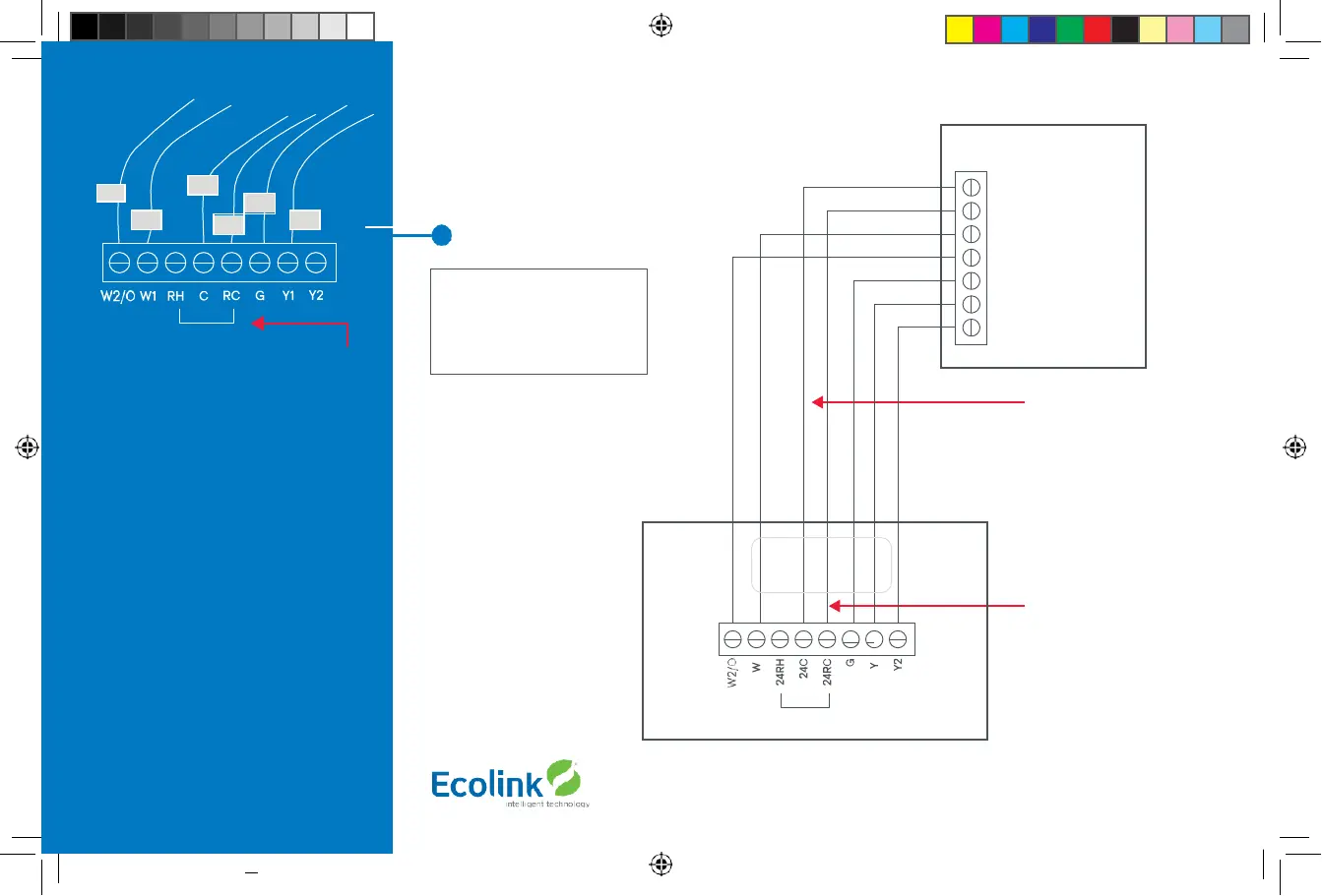
Heat Pump HVAC System Wiring
Single stage heating and cooling
Typical thermostat wiring colors.
Caution: verify that original wiring
matches. Colors may be different.
Blue
Red
Green
Yellow
Black/
brown
Heat Pump HVAC System
Thermostat connection
C 24VAC Common R
24VAC Return
W1 Aux Heat
O Changeover Valve
G Fan
Y1 Compressor Stage 1 Y2
Compressor Stage 2
Thermostat back
Factory installed RC/RH jumper
Most Heat Pump
systems have the C wire
and the thermostat can be
power by the 24VAC from
the HVAC system.
Batteries are not
required
for 24VAC powered systems.
If there is not a C wire
installed, the thermostat
MUST be powered from
batteries.
Connect the R wire to either
the RC or RH terminal.
DO NOT REMOVE THE
RC/RH JUMPER
Copyright © Ecolink Intelligent Technology
TBZ500_manual_8_5x5_5_inch Combined_RDN1240221.indd 10 24-02-2021 18:55
Factory installed RC and RH jumper.
Do not remove
Connect the wires as marked from the HVAC
system to the corresponding terminals on
the thermostat back.
*C wire (24VAC common) Heat Pump
systems usually have the C wire connected
to the thermostat. If there isn’t a C wire,
batteries must be installed.
** O (Orange) or B (Brown) wire (changeover
valve) connect to the W2/O terminal on the
thermostat.
NOTE: Be sure to set the correct changeover
operation (O = changeover with Cool, B =
changeover with Heat) in the SETUP menu.
Connect the R wire to either RC or
RH terminal.
Note!
If you get heating
when you expected cooling
or vice versa, change the
Change Over type to the
opposite setting.
 Loading...