XIV. ADDITIONAL
FIGURES
AND TABLES
Hanger
Assembly
--'-V
Note: Conceptual drawing
only. Please
fol1ow directions included
with
hanger
assembly
kit for
proper
inst-a1laf-ion.
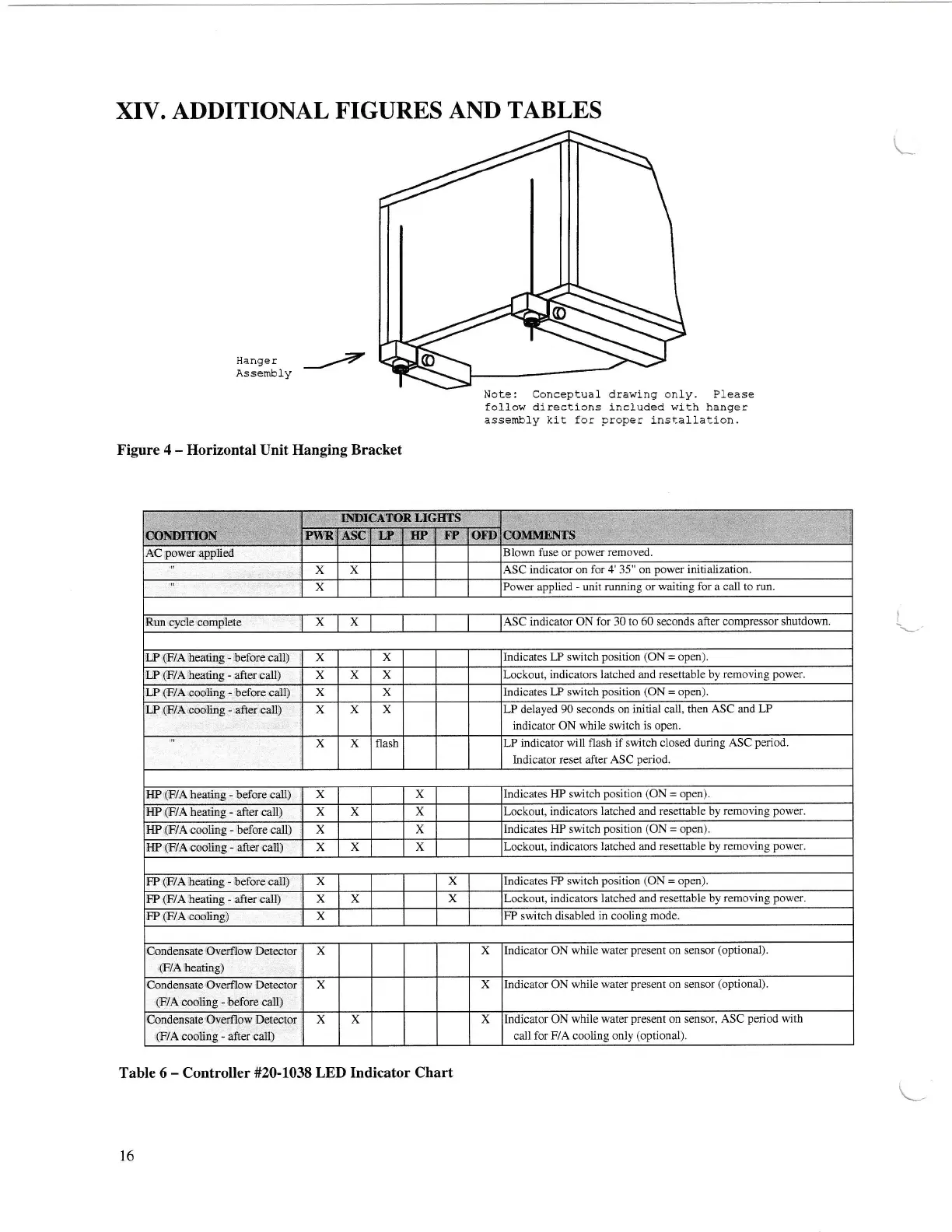
Figure 4
-
Horizontal Unit Hanging Bracket
Table 6
-
Controller
#20-1038 LED Indicator Chart
Blown fuse or
power
removed.
AC
power
applied
x
x ASC indicator on for
4'
35" on
power
initialization.
X Power applied
-
unit running or waiting
for
a call
to run.
Run
cycle complete
x X
ASC indicator ON for 30 to 60 seconds
after compressor shutdown.
Indicates
LP switch
position
(ON
=
open).
LP
(F/A
heating
-
before call)
X x
x x
x Lockout,
indicators latched and resettable by
removing
power.
LP
(F/A
cooling
-
before call)
x
x Indicates LP switch
position
(ON
=
open).
LP delayed 90 seconds
on initial call, then
ASC
and
LP
indicator ON while switch is open.
LP
(F/A
cooling - after call) x
x X
x
x flash LP indicator
will flash if switch ciosed during
ASC
period.
Indicator
reset a-fter ASC
period.
HP
(F/A
heating - before call)
x x
lndicates HP switch
position
(ON
=
open).
HP
(F/A
heating
-
after call)
x x
x Lockout, indicators
latched and resettable by removing
power.
t{P
(F/A
cooling
-
belore call) x
x
Indicates HP switch
position
(ON
=
open).
Lockout, indicators
latched
and
resettable by removing
power.
IIP
(F/A
cooling
-
after call) x
X x
Indicates FP switch
position
(ON
=
open).
x
x
FP
(F/A
heating
-
after call)
x X
x Lockout, indicators latched and
resettable by removing
power,
FP
switch
disabled in cooling
mode.
x
Condensate Overfl ow Detector
(F/A
heating)
x
x krdicator ON while
water
present
on
sensor
(optional).
x
x lndicator ON
while water
present
on sensor
(optional).
Condensate
Overllow Delector
(F/A
cooling
-
after call)
x x
x lndicator ON while
water
present
on
sensor, ASC
period
with
call for
F/A
cooling only
(optional).
I
I
16
LSND]?IOI{
COM}{[NTS.{sc
IF
m
r?
orD
LP
(F7A
heating
-
after call)
FP
(F/A
heating
-
before call)
FP
(F/A
cooling)
Condensate Overflow
Detector
(F/A
cooling
-
before call)