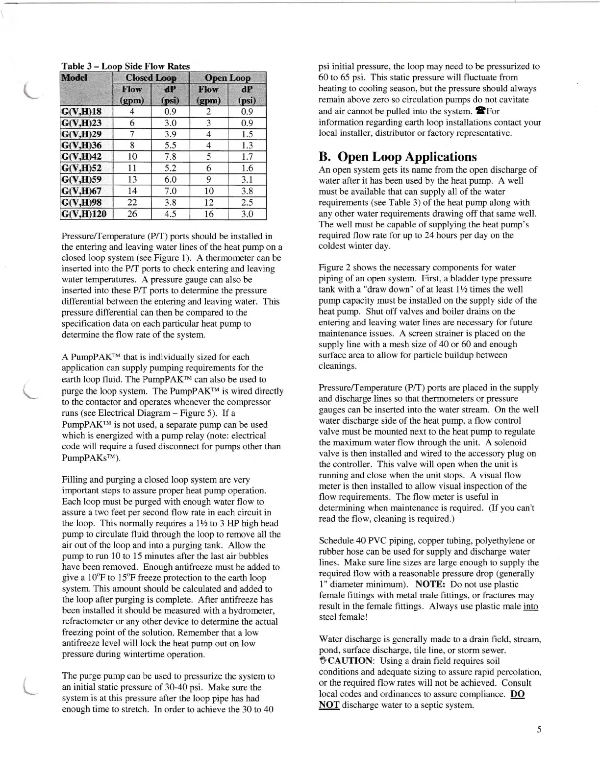
Table
3
-
Side
Flow Rates
Pressure/Temperature
(P/T)
ports
should
be installed in
the
entering
and leaving water
lines of the heat
pump
on a
closed loop system
(see
Figure
1). A thermometer can be
inserted into the P/T
ports
to check entering and leaving
water
temperatures. A
pressure
gauge
can also be
inserted into these P/T
ports
to determine the
pressure
differential between
the
entering
and
leaving water. This
pressure
differential
can
then
be compared
to
the
specification data
on each
particular
heat
pump
to
determine the flow rate
of
the
system.
A PumpPAKrM
that is
individually
sized for each
application can supply
pumping
requirements for the
earth loop fluid. The
PumpPAKrM can also be used
to
purge
the
loop
system. The PumpPAKrM is wired directly
to
the contactor and operates
whenever the
compressor
runs
(see
Electrical
Diagram
-
Figure 5). If a
PumpPAKrM is
not used, a separate
pump
can
be
used
which is energized with a
pump
relay
(note:
electrical
code will
require
a
fused disconnect for
pumps
other
than
PumpPAKsrM).
Filling
and
purging
a
closed
loop
system
are very
important steps to
assure
proper
heat
pump
operation.
Each loop must be
purged
with
enough
water
flow
to
assure a two
feet
per
second flow rate in each circuit in
the loop. This normally requires
a lYz to 3 HP high
head
pump
to circulate fluid through
the loop to remove all the
air out of the loop and into a
purging
tank.
Allow the
pump
to
run 10
to l5 minutes after
the
last
air bubbles
have been removed.
Enough antifreeze must
be added
to
give
a l0"F to l5oF freeze
protection
to the earth loop
system. This amount
should be calculated and added to
the loop
after
purging
is complete.
After antifreeze has
been installed it
should be measured with a hydrometer,
refractometer
or any other device
to determine the actual
freezing
point
of the
solution. Remember that
a low
antifreeze level will
lock the heat
pump
out on low
pressure
during wintertime
operation.
The
purge pump
can
be
used
to
pressurize
the
system
to
an initial
static
pressure
of 30-40
psi.
Make
sure the
system is at this
pressure
after the loop
pipe
has
had
enough time to stretch. In
order to
achieve
the
30 to
40
psi
initial
pressure,
the loop may need to be
pressurized
to
60 to 65
psi.
This
static
pressure
will
fluctuate from
heating
to cooling season, but the
pressure
should
always
remain
above
zero
so circulation
pumps
do
not
cavitate
and air
cannot be
pulled into
the system. SFor
information regarding
earth loop installations contact
your
local installer,
distributor or
factory
representative.
B.
Open
Loop Applications
An
open system
gets
its
name
from the open discharge of
water
after
it has
been used by the heat
pump.
A well
must
be available that can
supply
all of
the water
requirements
(see
Table 3) of the heat
pump
along
with
any other water requirements
drawing
off that
same
well.
The well must be capable of supplying the heat
pump's
required
flow
rate
for up to
24
hours
per
day on the
coldest
winter
day.
Fi_gure 2
shows
the necessary components for water
piping
of an
open
system.
First,
a bladder
type
pressure
tank with
a
"draw
down"
of
at
least
lVz
times
the
well
pump
capacity
must
be
installed
on the
supply
side
of the
heat
pump.
Shut off
valves and
boiler
drains on the
entering and
leaving water lines
are
necessary for future
maintenance issues. A screen strainer is
placed
on the
supply line with a mesh size of 40 or 60 and enough
surface area to allow for
particle
buildup
between
cleanings.
Pressure/Temperature
(P/T) ports
are
placed
in
the supply
and discharge
lines
so that
thermometers or
pressure
gauges
can
be inserted into the water stream. On the
well
water discharge side of the
heat
pump,
a
flow
control
valve
must be mounted next to the heat
pump
to regulate
the
maximum
water
flow
through
the unit.
A
solenoid
valve is
then
installed
and
wired
to the
accessory
plug
on
the controller. This valve will open when the unit is
running and close
when
the unit stops.
A visual
flow
meter
is then installed to allow
visual
inspection of the
flow
requirements. The
flow
meter is useful
in
determining when maintenance is required.
(If
you
can't
read
the flow, cleaning is
required.)
Schedule
40 PVC
piping,
copper tubing,
polyethylene
or
rubber hose can be used for supply
and
discharge water
lines. Make sure line
sizes
are large
enough to supply the
required
flow with a reasonable
pressure
drop
(generally
l"
diameter
minimum).
NOTE: Do not use
plastic
female fittings with
metal
male
fittings, or fractures
may
result
in the female fittings. Always
use
plastic
male
into
steel female !
Water
discharge is
_eenerally
made
to a drain field,
stream,
pond,
surface
discharge, tile line,
or storm sewer.
VCAUTION: Using a drain field requires
soil
conditions and adequate sizing to assure rapid
percolation,
or the required flow rates will not
be achieved. Consult
local
codes
and
ordinances to assure compliance. DO
pf
discharge water to a septic
system.
5
G(V,H)18
4
0.9
2
0.9
Gff.H)23
6
3.0 3 0.9
Gry.829
7
3.9
4
1.5
G(V,H)36 8 5.5 4 1.3
Gry,H)42
l0
7.8 5
1.7
G(v.H)s2
t1
5.2 6 1.6
G(V,H)s9
l3
6.0 9 3.1
G(V,H)67
11 1.0 10
3.8
22 3.8 12
2.s
G(v.H)120
26 4.5 t6
3.0
Closed Las:: O*n LoooMt{el
Flow
{pom)
a"
{ori}
II,orr
{qom}
dP
(osi)
Gry.m98
L
L