32
This manual is the intellectual property of Ecoso. Copying and reprinng is prohibited. © 2016
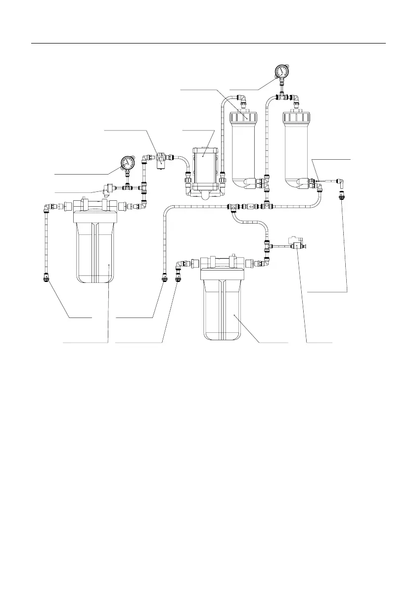
INSTALLER AND USER GUIDE FOR REVERSE OSMOSIS SYSTEM ECOSOFT ROBUST 1000, ROBUST 3000
ROBUST 3000
Water inlet
connection
Sediment
pre-filter
Inlet solenoid valve
Inlet pressure
gauge
Low-pressure
switch
Booster
pump
Membrane
module
Operating
pressure
gauge
Flow restrictor
Drain outlet
High-pressure
switch
Carbon
post-filter
Tank
connection
Permeate outlet
Figure 3
Technological scheme of RObust 3000 is shown in Figure 2. Aer the pre-lters, the pressure
booster pump feeds the water to the reverse osmosis membrane array. Permeate from both
modules goes to the permeate collector, and the concentrate from the 1
st
module goes to the 2
nd
one. Second stage permeate goes to the permeate collector, and concentrate is discarded to drain
via concentrate ow restrictor and drain port in port rack. Pressure gauge no. 2 shows pressure
between two membranes. Permeate goes to the puried water line or pressure tank (if installed),
passing through the carbon post-lter. Puried water line may go to the puried water faucet (not
included) or be connected with some other consumer appliance. High-pressure switch installed
before the post-lter reads pressure in permeate line and starts the reverse osmosis system when it
drops (due to taking of some water from the pressure tank or opening puried water faucet). When
the system switches on, entry solenoid valve is opened and booster pump is powered up, which
allows to feed water into the system. When puried water stops being drawn from the system,
pressure starts to build up and closes high-pressure switch switching o the system.
RObust 3000 system has low feed water pressure protecon implemented with a low-pressure
switch, which prevents the pump and solenoid from operang if feed pressure is less than
0.4 bar (5.8 psi). Two pressure gauges on the front panel show operang pressure in the system,
which allows diagnosing potenal and occurring problems.