34
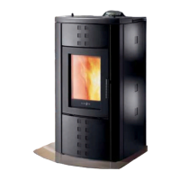
First of all check that the relief valve ( 1 ), situated on the upper right hand side of the boiler (see Figure
24 and Figure 25) is open once the water has been lled as shown in the gure below.
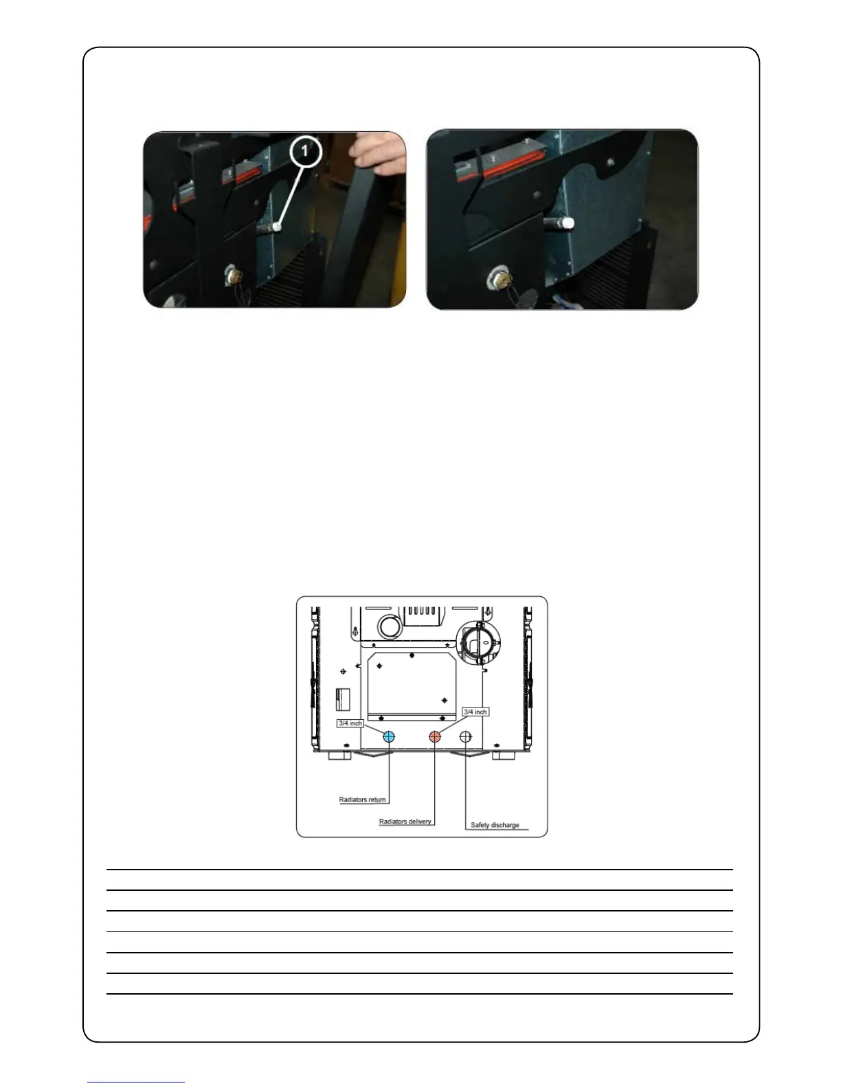
Connect the boiler connectors correctly (see Figure 26) to the hydraulic plant, bringing the plant pressure
between 1.0 – 2.5 bar ( if it is an open tank plant and not a closed one, the setting in the menu reserved
for the authorised technician must be changed).
Now bleed the hydraulic plant from the valve tted on the boiler or from the valves tted onto the
radiators. This operation can also be carried out several times after the boiler has been started, since
the air bubbles will tend to go up to the top of the boiler when the water temperature starts increasing.
While the boiler is being bled, make sure that the electrical parts near the valve do not get wet!
If this should happen, do not light the boiler but proceed with drying the electronic mother board using
a hair dryer.
Hydraulic installation examples
Legend
RA : Radiators CI : Plant manifold
AL : Feed from water mains VM : Mixer valve
MI : Plant manifold ACS : Hot sanitary water
RI : Plant return T : Thermostat graduated up to 120°C
V1 : Outward valve M : Radial manometer scale 0 - 4 bar
V2 : Return vale SP : Plate exchanger
V : Ball valve RP : Pressure reducer
Figure 24. Figure 25.
Figure 26.
 Loading...