o--ring (2)
turbine
support
clip (2)
copper tube (2)
VALVE INLET
copper
tube
o--ring
clip
turbine
support
A.
B.
Bypass
Valve
Installation
copper
tube (2)
o--ring (2)
10
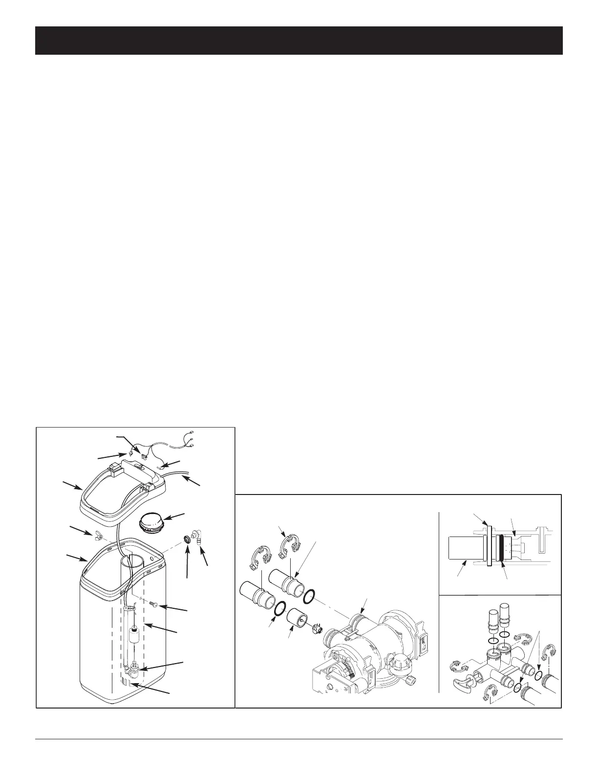
e. Take the rubber grommet and hose adaptor elbow from the
parts bag. Push grommet into the hole in the back of the
b
rine tank. Then insert the larger diameter end of the elbow
through the grommet.
f. Locate the brine tank cable, one end of which is shipped
plugged into the back of the electronic controller (PWA). At
the loose end of this cable, identify the tank light, salt level
sensor and cover sensor. Insert each of these three items
i
nto their corresponding slots in the rim, as shown in Figure 4.
g. Route the cable through the clip at the back of the rim.
h. Snap the brine tank cover assembly onto the rim, being
c
areful not to pinch the wires of the brine tank cable.
3. INSTALL BYPASS VALVE and/or COPPER
TUBES
a. If installing an EcoWater Systems Bypass Valve, put
lubricated o-ring seals onto both bypass valve ports (See
Figure 5B). Carefully slide the bypass valve into the condi-
tioner/refiner valve and install the "C" clips.
b. Slide a lubricated o-ring seal onto each of the copper
tubes. Carefully insert the copper tubes into the bypass valve
(See Figure 5B), or into the conditioner/refiner valve (Figures
5 & 5A). Then install the “C'' clips.
NOTE: For lubrication, use silicone grease approved for
potable water supplies.
4. TURN OFF WATER SUPPLY
a. Close the main water supply valve near the well pump or
water meter.
b. Shut off the electric or fuel supply to the water heater.
c. Open high and low faucets to drain all water from the
house pipes.
5. INSTALLING THREE-VALVE BYPASS
If installing a 3-valve bypass system, plumb as needed using
Figure 3 as a guide. When installing sweat copper, be sure to
use lead-free solder and flux, required by federal and state
codes. Use pipe joint compound on outside pipe threads.
1. UNPACKING
EcoWater Systems conditioner/refiner models R20, R30 and
R40 are shipped from the factory in one carton. The carton
also includes a bag of small parts needed to assemble and
install the unit, plus this manual.
EcoWater Systems conditioner/refiner models R50 and R70
are shipped from the factory in two cartons. One contains the
resin tank/controller assembly, a bag of small parts needed to
assemble and install the unit, plus this manual. The other
c
ontains the assembled brine tank.
T
horoughly check the EcoWater Systems conditioner/refiner
for possible shipping damage and parts loss. Also inspect
and note any damage to the shipping carton. Notify the trans-
portation company if damage is present. EcoWater Systems
is not responsible for in-transit damages.
Remove and discard (RECYCLE) all packing materials. We
suggest you keep the small parts in the bag until you are
ready to use them.
2. BRINE TANK (on two-tank models)
Complete all steps below for R20, R30 and R40 models. For
models shipped with an assembled brine tank (R50 and R70),
unsnap the brine tank cover assembly from the rim (pull on
the hand hold along the back) and do steps f through h.
a. Snap the rim into place on the brine tank (See Fig. 4).
b. Lower the brinewell, with the slots at the bottom, into the
brine tank. Then use the screw and nut from the parts bag to
fasten the brinewell in place along the side of the tank.
c. Lower the brine valve into the brinewell. Push the tubing
into the brinewell top slot (Fig. 4) and route it out through the
hole in the back of the rim.
d. Install the brinewell cover.
FIG. 5
ECOWATER
S Y S T E M S
Unpacking & Installation
FIG. 4
Nut
Brine
tank
Rim
Slots
Screw
Brine
valve
Brinewell
Grommet
Elbow
Brinewell
cover
Brine
tubing
Tank light
Salt level sensor
Lid sensor
Cable
to
Controller