5
Introducing the Motherboard
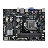
Table of Motherboard Components
This concludes Chapter 1. The next chapter explains how to install the motherboard.
1 CPU Socket LGA775 socket for P4/Celeron CPUs
2 CPU_FAN CPU cooling fan connector
3 DIMM1~DIMM4 184-pin DDR SDRAM slots
6 ATX1 Standard 20-pin ATX power connector
5 FDD1 Floppy disk drive connector
7 IDE1 Primary IDE connector
8 IDE2 Secondary IDE connector
11 CLR_CMOS Clear CMOS jumper
14 BIOS_WP BIOS flash protect jumper
13 PANEL1 Front panel switch/LED header
23 AGP1 AGP Express slot
15 USB3-4 Front Panel USB headers
21 PCI1~PCI3 32-bit add-on card slots
9 SPK1 Speaker header
20 CD_IN Analog audio input connector
24 AUDIO1 Front panel audio header
26 ATX12V 4-pin +12V power connector
25 SYS_FAN Case cooling fan connector
LABEL COMPONENT
18 CNR1* Communications Networking Riser slot
19 SPDIFO1 SPDIF out header
12 SATA1~2 Serial ATA connectors
10 PWR_FAN Power cooling fan connector
17 COM2 Onboard serial port header
4 IR1 Onboard infrared header
16 1394A2* Onboard 1394a header
“*” stands for optional components.
22 JP4 LAN Enable/Disable jumper