Do you have a question about the ECS 865G-M8 and is the answer not in the manual?
States the certifying body and adherence to TÜV CERT procedure.
Lists the certified companies and their addresses.
Details the scope of the quality system.
Confirms fulfillment of ISO 9001:2000 requirements.
Provides certificate registration number and validity period.
Identifies the certified company.
Details the awarded certificate for the Environmental Management System.
Confirms compliance with the ISO14001:1996 standard.
Defines the area of application for the Environmental Management System.
States the date of issue and expiry for the certificate.
Outlines copyright restrictions for the publication.
States the manufacturer's disclaimers and right to change content.
Lists recognized product trademarks.
Details FCC compliance for Class B digital devices and interference.
States device compliance with FCC rules and conditions.
Confirms compliance with Canadian Interference-causing Equipment Regulations.
Lists the chapters and their descriptions within the manual.
Provides an overview of the 865G-M8 motherboard and its target market.
Describes the 865G Northbridge and ICH5 Southbridge chipsets.
Details PCI slots, USB ports, IDE connectors, SATA ports, and rear I/O.
Lists features related to the LGA775 socket and CPU compatibility.
Details specifications for the 865G Northbridge and ICH5 Southbridge.
Describes DDR SDRAM support and capacity.
Lists features related to the integrated graphics accelerator.
Describes AC'97 2.3 compliant audio CODEC features.
Lists available expansion slots like PCI, AGP, SATA, and CNR.
Details features of the optional onboard LAN controller.
Lists the standard I/O ports available on the motherboard.
Mentions Award BIOS features for system configuration.
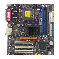
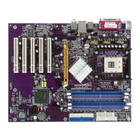
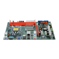
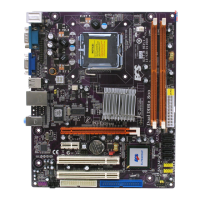
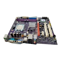
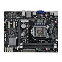
Illustrates and labels the physical components of the motherboard.
Provides a detailed list of motherboard components with labels and functions.
Lists essential safety measures to follow during motherboard installation.
Advises on selecting a compatible computer case for the motherboard.
Guides on physically mounting the motherboard inside a computer case.
Explains how to check and set motherboard jumpers for configuration.
Illustrates and defines the states of 2-pin and 3-pin jumpers.
Shows the locations of CLR_CMOS and BIOS_WP jumpers on the motherboard.
Details the type, description, and default settings for jumpers.
Guides on connecting CPU fan, case fan, speaker, and front panel connectors.
Explains the pinout and function of the CPU fan power connector.
Explains the pinout and function of the system fan power connector.
Details the pinout for the internal speaker connector.
Lists the pinout and function of the 20-pin ATX power connector.
Lists the pinout and function of the 4-pin ATX12V power connector.
Explains the pinout for front panel switches and LEDs.
Describes how to connect the hard drive activity LED.
Explains connecting LEDs for power, sleep, and message waiting status.
Guides on connecting a momentary-contact switch for system reset.
Explains connecting a momentary-contact switch for power on/off.
Provides instructions and cautions for installing the CPU.
Advises on CPU clock/bus frequency settings and overclocking warnings.
Step-by-step guide for physically installing the CPU onto the socket.
Provides important notices regarding CPU installation and thermal management.
Guides on installing DDR SDRAM memory modules into DIMM slots.
Lists compatible DDR SDRAM modules and their bus speeds.
Step-by-step instructions for inserting memory modules into slots.
Lists tested and qualified DDR400 memory modules by vendor.
Guides on installing IDE devices like hard drives and CD-ROM drives.
Explains primary and secondary IDE channels and ribbon cable usage.
Specifies connecting the first hard drive to the primary IDE connector.
Details connecting the second drive to the secondary IDE connector.
Describes the two SATA connectors for Serial ATA devices.
Provides instructions for connecting SATA hard drives using SATA cables.
Guides on connecting a floppy diskette drive using the FDD1 interface.
Details the floppy disk connector and ribbon cable usage.
Explains how to install expansion cards into PCI, AGP, and CNR slots.
Describes the AGP slot's purpose and specifications.
Details the three standard PCI slots and their compliance.
Explains the optional CNR slot for modem and audio functionality.
Provides step-by-step instructions for installing an add-on card.
Advises on installing drivers and software for certain add-on cards.
Guides on connecting optional devices like SPDIF and front panel audio.
Details the SPDIF out header for digital audio output.
Explains the front panel audio header for microphone and line-out.
Details the pinout for front panel USB headers.
Explains the pinout for Serial ATA connectors.
Details the pinout for the infrared header.
Details the pinout for the CD audio input header.
Details the pinout for the auxiliary audio input header.
Guides on connecting various I/O devices to the motherboard ports.
Explains the use of PS/2 ports for mouse and keyboard.
Guides on connecting printers and serial devices.
Explains connecting monitors and network cables.
Describes the use of USB ports and audio jacks.
Introduces the BIOS Setup Utility and its purpose.
Suggests when to use the standard configuration and for troubleshooting.
Explains how to access the BIOS Setup Utility after POST.
Instructs to press the DEL key to enter the BIOS Setup Utility.
Lists and explains the function of BIOS navigation keys.
Provides steps for downloading and installing updated BIOS.
Details the process of creating a bootable disk and flashing the BIOS.
Displays basic system information and allows configuration.
Explains how to set the system date and time.
Guides on configuring IDE channels and devices (Master/Slave).
Describes how to automatically detect IDE hard drive parameters.
Explains settings for IDE channel master/slave auto-detection and manual configuration.
Defines ways to access IDE hard disks, such as LBA.
Covers settings for the floppy disk drive and 3-mode support.
Explains video mode settings and POST error handling.
Shows base, extended, and total memory detection (display only).
Defines advanced system information and boot settings.
Details CPU-specific features like thermal management.
Sets the delay time before the CPU enters auto thermal mode.
Displays CPU temperature and sets safe temperature thresholds.
Adjusts throttled performance frequency and voltage.
Configures advanced CPU features like C1E, Vanderpool, and SpeedStep.
Sets the order for booting from hard disk drives.
Configures L3 cache and Hyper-Threading technology.
Shortens the Power-On Self Test (POST) for faster startup.
Sets the priority order for boot devices (Floppy, Hard Disk, CDROM).
Configures floppy drive seek and keyboard NumLock status.
Manages legacy software compatibility with system memory access.
Sets keyboard typematic rate and delay.
Configures password requirements for system access or setup.
Manages APIC mode and DRAM settings for specific OS.
Enables or disables S.M.A.R.T. diagnostics for hard drives.
Sets a delay for hard disk identification during boot.
Defines critical timing parameters of the motherboard chipset.
Selects CAS latency time based on installed DRAM.
Controls the timing delay before DRAM read command.
Sets precharge time for DRAM accumulation before refresh.
Inserts delay between CAS and RAS strobe signals for DRAM access.
Sets CPU clocks for Row Address Strobe signal accumulation.
Sets the main memory frequency, especially with external graphics.
Caches System BIOS for faster execution.
Caches Video RAM for better performance.
Defines the aperture size for AGP graphics adapters.
Chooses the primary display card for initialization.
Optimizes data transfer from CPU to GMCH and DDR400 performance.
Increases CPU L2 cache timing performance and sets onboard frame buffer size.
Sets the boot display function to Auto, CRT, EFP, or TV.
Defines operation of peripheral components on system I/O ports.
Configures onboard IDE devices, including block mode and PIO/UDMA.
Enables block transfer for optimal IDE drive performance.
Activates primary and secondary IDE channels for device support.
Assigns PIO and UDMA modes for IDE devices.
Enables/disables ATA 66/100 Cable Message display.
Selects SATA mode and enables/disables on-chip Serial ATA.
Selects the master mode for SATA ports.
Configures onboard devices like USB, AC97 audio/modem, and LAN.
Enables or disables the USB controller.
Enables or disables the USB 2.0 controller.
Allows USB keyboard/mouse interaction with DOS and legacy OS.
Controls onboard AC97 audio and modem devices.
Enables/disables onboard LAN and its boot ROM.
Configures Super I/O devices including power on functions, serial/parallel ports.
Sets system power-on methods like hot key or password.
Enables or disables the onboard floppy disk controller.
Manages UART 2 mode control and selects communication protocol.
Configures IR reception/transmission polarity and delay.
Determines infrared function and IR pin settings.
Configures onboard parallel port and its transfer mode (SPP, ECP, EPP).
Configures DMA channels for ECP mode parallel port.
Sets system behavior after power failure.
Controls system power management modes and timeouts.
Defines suspend mode as S1 (POS) or S3 (STR).
Initializes VGA BIOS during S3 resume.
Configures video power saving methods.
Sets suspend type to Stop Grant and specifies modem IRQ.
Configures suspend mode and hard drive power down.
Controls software power down via the power button.
Enables system wake-up from power saving modes.
Configures system wake-up by scheduled alarms.
Lists events that wake the system and IDE activity resume.
Configures the PCI bus system and I/O device operations.
Clears Plug and Play configuration data from BIOS.
Manages dynamic resource allocation for Plug and Play devices.
Overcomes problems with non-standard VGA cards.
Assigns IRQ for onboard USB interfaces.
Identifies interrupt request lines for PCI devices.
Monitors critical voltages, temperatures, and fan speeds.
Enables/disables system fan speed control.
Sets CPU temperature thresholds for fan control.
Manually sets smart fan startup and stop duty-cycles.
Sets target temperature for throttling and shutdown temperature.
Displays system component data (CPU temp, fan speed, voltage).
Sets CPU clock speed and system bus frequency.
Adjusts CPU clock ratio and auto-detects clock settings.
Manages spread spectrum for EMI reduction and sets CPU clock.
Loads fail-safe default settings for system stability.
Loads optimized default settings for performance.
Sets or disables supervisor and user passwords.
Saves changes and exits the BIOS Setup Utility.
Discards changes and exits the BIOS Setup Utility.
Introduces the support CD-ROM contents and usage guidelines.
Guides on using the auto-install feature for drivers and software.
Explains the Setup, Browse CD, and Exit options on the auto-install screen.
Provides step-by-step instructions for running the setup program.
Guides on selecting features and proceeding with installation.
Details the steps in the InstallShield Wizard for software installation.
Guides on manual driver installation using PATH.DOC.
Provides information on available utility software and licensing.
Describes the utility for erasing and writing system BIOS.
Explains the Windows-based utility for BIOS flashing.
| Brand | ECS |
|---|---|
| Model | 865G-M8 |
| Category | Motherboard |
| Language | English |