27
Installing the Motherboard
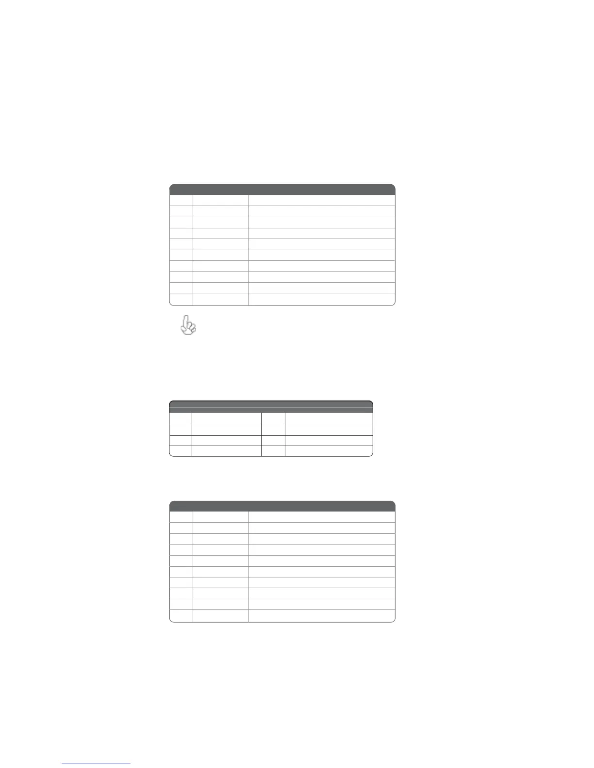
USB3/4: Front Panel USB headers
The motherboard has four USB ports installed on the rear edge I/O port array. Additionally,
some computer cases have USB ports at the front of the case. If you have this kind of case,
use auxiliary USB connector to connect the front-mounted ports to the motherboard.
Please make sure that the USB cable has the same pin assignment as
indicated above. A different pin assignment may cause damage or system
hang-up.
1 USBPWR Front Panel USB Power
2 USBPWR Front Panel USB Power
3 USB_FP_P0- USB Port 0 Negative Signal
4 USB_FP_P1- USB Port 1 Negative Signal
5 USB_FP_P0+ USB Port 0 Positive Signal
6 USB_FP_P1+ USB Port 1 Positive Signal
7 GND Ground
8 GND Ground
9 Key No pin
10 USB_FP_OC0 Overcurrent Signal
Pin Signal Name Function
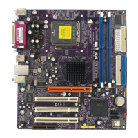
SATA1/2: Serial ATA connectors
These connectors are use to support the new Serial ATA devices for the highest date transfer
rates (150 MB/s), simpler disk drive cabling and easier PC assembly. It eliminates limitations
of the current Parallel ATA interface. But maintains register compatibility and software
compatibility with Parallel ATA.
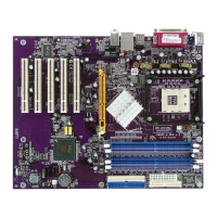
COM2: Onboard serial port header
Connect a serial port extension bracket to this header to add a second serial port to your
system.
Pin Signal Name Function
1 Ground 2 TX+
3 TX- 4 Ground
5 RX- 6 RX+
7 Ground - -
Pin Signal Name Pin Signal Name
1 NDCDB Data carry detect
2 NSINB Serial Data In
3 NSOUTB Serail Data Out
4 NDTRB Data terminal ready
5 GND Ground
6 NDSRB Date set ready
7 NRTSB Request to send
8 NCTSB Clear to send
9 NRIB Ring Indicator
10 KEY Key
Pin Signal Name Function