5
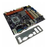
Introducing the Motherboard
Table of Motherboard Components
This concludes Chapter 1. The next chapter explains how to install the motherboard.
1 CPU Socket LGA775 socket for Pentium 4 CPUs
3 CPU_FAN CPU cooling fan connector
15 COM2 Onboard serial port header
11 PWR_FAN Power fan connector
16 F_USB1~F_USB2 Front Panel USB headers
13 SATA1~4 Four serial ATA connectors
9 CLR_CMOS Clear CMOS jumper
7 ATX1 Standard 24-pin ATX power connector
14 F_PANEL Front Panel switch/LED header
6 FDD Floppy diskette drive connector
19 CDIN1 Primary CD-in connector
20 F_AUDIO1 Front panel audio header
LABEL COMPONENT
8 IDE1 Primary IDE channel
4 DIMM1~4 Four 184-pin DDR SDRAM slots
12 IRDA Infrared header
23 PCIEX16 PCI Express X16 Graphics card slot
21 SPDIF-O1 SPDIF out header
2 SYS_FAN System fan connector
24 ATX12V ATX12V power connector
22 SPDIF-I1 SPDIF out header
18 PCI1~3 Three 32-bit add-on card slots
17 BIOS_WP BIOS flash protect jumper
10 SPK1 Speaker header
5 CHS1 Chasis intrusion detection header