24
Installing the Motherboard
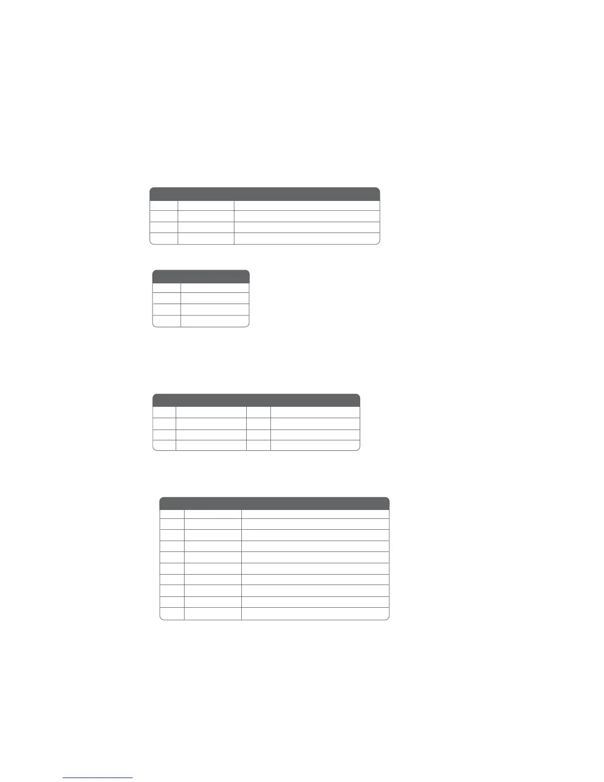
AUXIN1: Auxiliary-in connector
This connector is an additional line-in audio connector. It allows you to
attach a line-in cable when your rear line-in jack is set as line out port for 4-
channel function.
1 AUXIN_L AUX In left channel
2 AGND Ground
3
AGND Ground
4
AUXIN_R AUX In right channel
Pin Signal Name Function
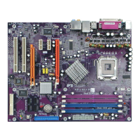
CDIN1: Primary CD-in connector
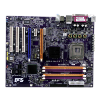
SATA1/2/3/4: Serial ATA connectors
These connectors are use to support the new Serial ATA devices for the highest date transfer
rates (150 MB/s), simpler disk drive cabling and easier PC assembly. It eliminates limitations
of the current Parallel ATA interface. But maintains register compatibility and software
compatibility with Parallel ATA.
1 CD _L
2 GND
3 GND
4 CD _R
Pin Signal Name
Pin Signal Name Function
1 Ground 2 TX+
3 TX- 4 Ground
5 RX- 6 RX+
7 Ground - -
Pin Signal Name
Pin Signal Name
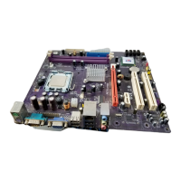
COM2: Onboard serial port header
Connect a serial port extension bracket to this header to add a second serial port to your
system.
1 NDCDB Data carry detect
2 NSINB Serial Data In
3 NSOUTB Serial Date Out
4 NDTRB Data terminal ready
5 GND Ground
6 NDSRB Date set ready
7 NRTSB Request to send
8 NCTSB Clear to send
9 NRIB Ring Indicator
10 Key No pin
Pin Signal Name Function