9
Installing the Motherboard
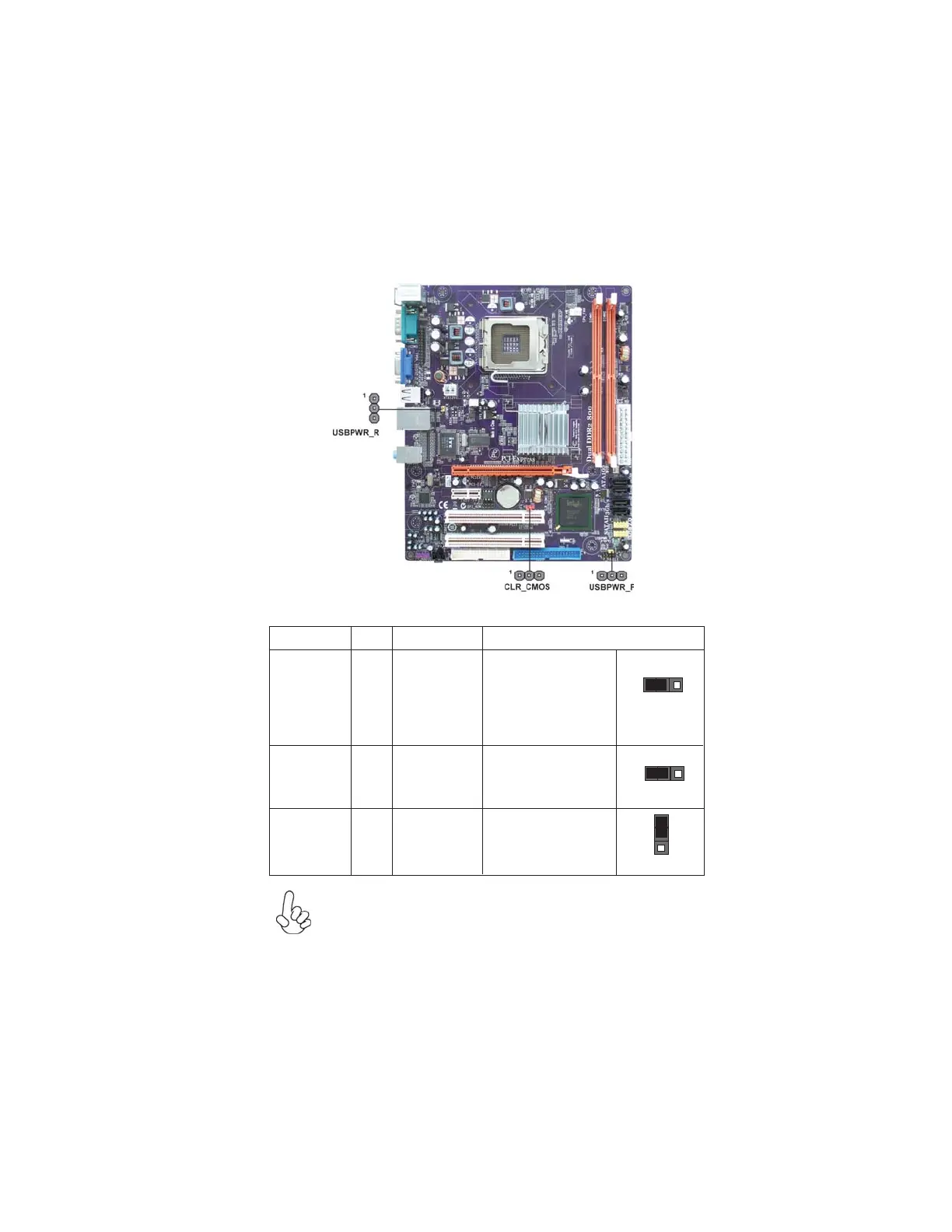
Checking Jumper Settings
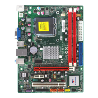
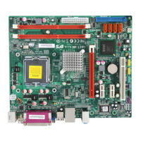
The following illustration shows the location of the motherboard jumpers. Pin 1 is
labeled.
Jumper Settings
USBPWR_F
USBPWR_R
Jumper
Type
Description Setting (default)
CLR_CMOS
3-pin
Clear CMOS
1-2: NORMAL
2-3: CLEAR CMOS
Before clearing the
CMOS, make sure to
turn off the system.
CLR_CMOS
1
USBPWR_F
3-pin
USBPWR_R 3-pin
Rear USB PS/2
Power Select
Jumper
2-3: 5VSB
1-2: VCC
1
Front Panel
Select Jumper
USB Power
1-2: VCC
2-3: 5VSB
1. To avoid the system instability after clearing CMOS, we recommend
users to enter the main BIOS setting page to “Load Optimal Defaults”
and then “Save Changes and Exit”.
2. Make sure the power supply provides enough 5VSB voltage before
selecting the 5VSB function.
3. It is required that users place the USBPWR_F & USBPWR_R cap onto
2-3 pin rather than 1-2 pin as default if you want to wake up the com-
puter by USB/PS2 KB/Mouse.
1
 Loading...