17
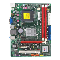
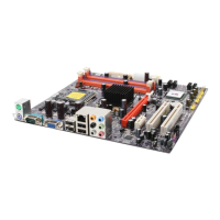
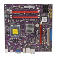
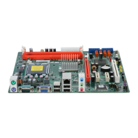
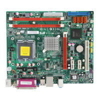
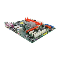
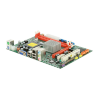
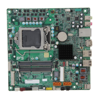
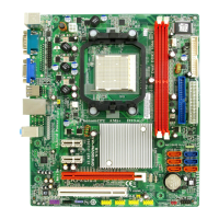
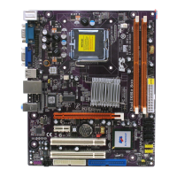
Installing the Motherboard
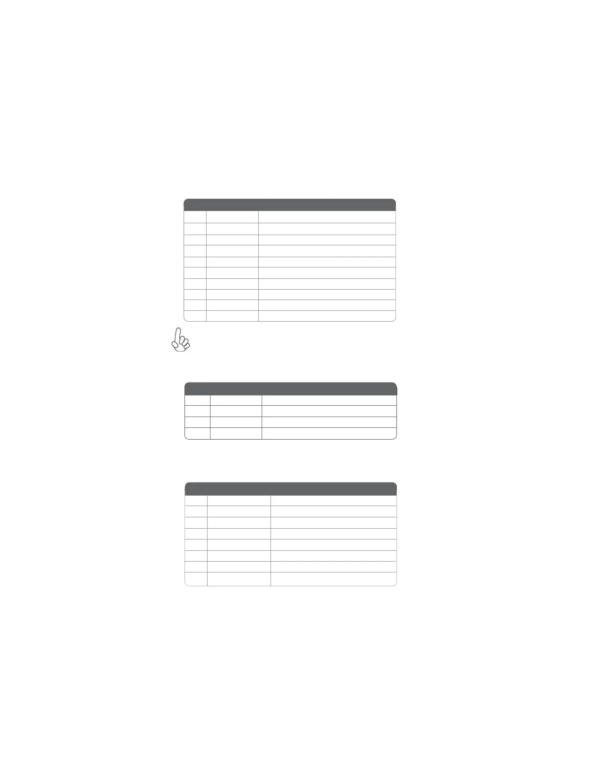
F_USB1~2: Front Panel USB headers
The motherboard has four USB ports installed on the rear edge I/O port array.
Additionally, some computer cases have USB ports at the front of the case. If you
have this kind of case, use auxiliary USB connector to connect the front-mounted
ports to the motherboard.
Please make sure that the USB cable has the same pin assignment as
indicated above. A different pin assignment may cause damage or system
hang-up.
1 USBPWR Front Panel USB Power
2 USBPWR Front Panel USB Power
3 USB_FP_P0- USB Port 0 Negative Signal
4 USB_FP_P1- USB Port 1 Negative Signal
5 USB_FP_P0+ USB Port 0 Positive Signal
6 USB_FP_P1+ USB Port 1 Positive Signal
7 GND Ground
8 GND Ground
9 Key No pin
10 USB_FP_OC0 Overcurrent signal
Pin Signal Name Function
CD_IN1: Analog Audio Input connector
Pin Signal Name Function
1 CD_L CD In left channel
2 GND Ground
3 GND Ground
4 CD_R CD In right channel
SPI_ROM: SPI ROM header
This 4 Mb ROM contains the programmable BIOS program.
1 CHIP SELECT Select chip
2 VCC VCC
3 DATA OUTPUT data output
4 HOLD hold
5 WRITE PROTECT BIOS write protect
6 CLOCK clock
7 CND CND
8 DATA INPUT data input
Pin Signal Name
Function
 Loading...