19
Installing the Motherboard
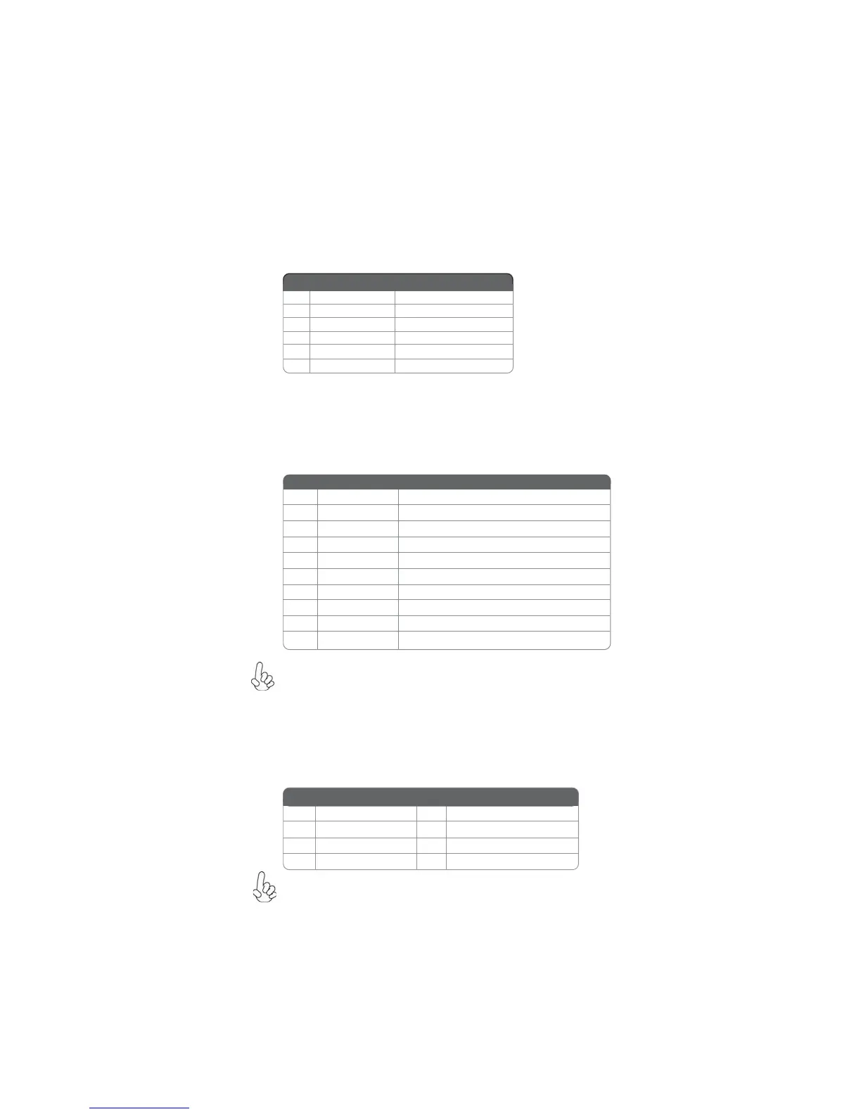
IR: Infrared header
The motherboard supports an Infrared (IR) data port. Infrared ports allow the wire-
less exchange of information between your computer and similarly equipped devices
such as printers, laptops, Personal Digital Assistants (PDAs), and other computers.
1 Not Assigned Not assigned
2 Key No pin
3 +5V IR Power
4 GND Ground
5 IR_TX IrDA serial output
6 IR_RX IrDA serial input
Pin Signal Name Function
F_USB1~3: Front Panel USB headers
The motherboard has six USB ports installed on the rear edge I/O port array. Addi-
tionally, some computer cases have USB ports at the front of the case. If you have
this kind of case, use auxiliary USB connector to connect the front-mounted ports to
the motherboard.
Please make sure that the USB cable has the same pin assignment as
indicated above. A different pin assignment may cause damage or system
hang-up.
1 USBPWR Front Panel USB Power
2 USBPWR Front Panel USB Power
3 USB_FP_P0- USB Port 0 Negative Signal
4 USB_FP_P1- USB Port 1 Negative Signal
5 USB_FP_P0+ USB Port 0 Positive Signal
6 USB_FP_P1+ USB Port 1 Positive Signal
7 GND Ground
8 GND Ground
9 Key No pin
10 NC Not connected
Function
Pin Signal Name
SATA1~5: Serial ATA connectors
These connectors are used to support the new Serial ATA devices for the highest date
transfer rates (3.0 Gb/s), simpler disk drive cabling and easier PC assembly. It elimi-
nates limitations of the current Parallel ATA interface. But maintains register com-
patibility and software compatibility with Parallel ATA.
Due to the limitation of NVIDIA chipset, SATA 4~5 support AHCI/RAID
Mode only.
1 Ground 2 TX+
3 TX- 4 Ground
5 RX- 6 RX+
7 Ground - -
Pin Signal Name
Pin Signal Name