14
Installing the Motherboard
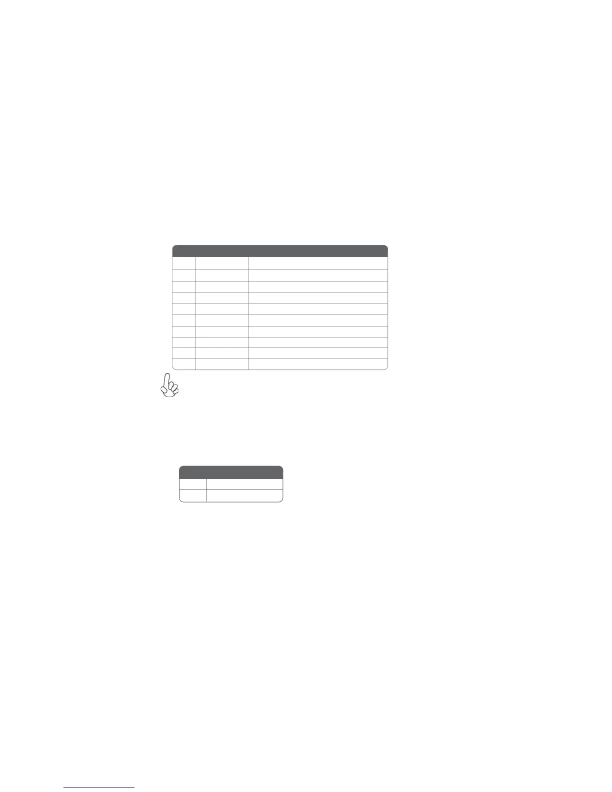
F_USB1~2: Front Panel USB 2.0 headers (F_USB1 supports EZ charger)
The motherboard has two USB 2.0 ports installed on the rear edge I/O port array.
Additionally, some computer cases have USB 2.0 ports at the front of the case. If you
have this kind of case, use auxiliary USB 2.0 connectors to connect the front-
mounted ports to the motherboard.
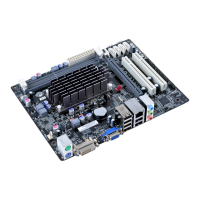
CASE: Chassis Intrusion Header
This detects if the chassis cover has been removed. This function needs a chassis
equipped with instrusion detection switch and needs to be enabled in BIOS.
Short Chassis cover is removed
Open Chassis cover is closed
Pin 1-2 Function
Unlike F_USB2 in this motherboard, F_USB1 supports EZ charger technology, pro-
vides about 1A current than general USB port in off mode for USB devices. It is useful
and excellent, especially for the iPhone, iPad and iPod touch devices that need a
large amount of current for faster recharging within less time.
Please make sure that the USB cable has the same pin assignment as
indicated above. A different pin assignment may cause damage or system
hang-up.
1 USBPWR Front Panel USB Power
2 USBPWR Front Panel USB Power
3 USB_FP_P0- USB Port 0 Negative Signal
4 USB_FP_P1- USB Port 1 Negative Signal
5 USB_FP_P0+ USB Port 0 Positive Signal
6 USB_FP_P1+ USB Port 1 Positive Signal
7 GND Ground
8 GND Ground
9 Key No pin
10 USB_FP_OC0 GND
Pin Signal Name Function