Do you have a question about the ECS HDC-I and is the answer not in the manual?
Legal notice regarding reproduction and use of the publication.
States that information is subject to change without notice and disclaims warranties.
Acknowledges registered trademarks of Microsoft and Intel.
Details FCC compliance for Class B digital devices and potential interference.
States compliance with Canadian Interference-causing Equipment Regulations for Class B apparatus.
Introduces the motherboard and its basic features and components.
Guides users through the physical installation of the motherboard.
Explains how to navigate and use the system's BIOS setup utility.
Details how to install drivers and utilities from the included software disc.
Provides guidance on diagnosing and resolving common hardware issues.
Welcomes the user and provides a brief overview of the motherboard's purpose.
Lists and describes the key features and capabilities of the motherboard.
Details the technical specifications of the motherboard hardware components.
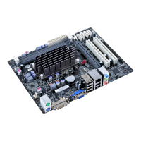
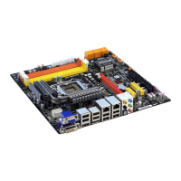
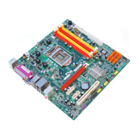
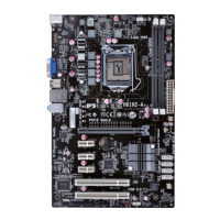
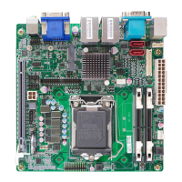
Identifies and labels the physical components on the motherboard.
Outlines essential safety guidelines to follow during motherboard installation.
Provides advice on selecting a compatible computer case for the motherboard.
Describes the process of physically mounting the motherboard inside a computer case.
Explains how to install expansion cards into available slots on the motherboard.
Describes the SPDIFO output port.
Mentions the onboard Bluetooth connectivity.
Describes the DVI video output port.
Describes the VGA video output port.
Details the available USB 2.0 and USB 3.0 ports.
Describes the LAN network port.
Describes the eSATA external storage port.
Describes the HDMI video/audio output port.
Describes the audio jacks for microphone and line-in/out.
Lists configurable system features available through the BIOS.
Specifies the CPU details for the motherboard.
Specifies the chipset used on the motherboard.
Details memory specifications, including type and capacity.
Lists the types and number of expansion slots available.
Outlines storage interface specifications, like SATA ports.
Specifies the audio codec used on the motherboard.
Details the specifications for the onboard LAN controller.
Lists all input/output ports available on the motherboard's rear panel.
Describes internal connectors and headers for case connections.
Provides information about the system's BIOS.
States the physical dimensions and form factor of the motherboard.
A table identifying labeled components on the motherboard diagram.
Step-by-step guide for installing DDR3 SDRAM modules into the motherboard slots.
Detailed procedure for correctly installing memory modules into DIMM slots.
Explains how to use jumpers to configure system settings on the motherboard.
Details specific jumper settings, such as for clearing CMOS.
Explains how to install expansion cards into available slots on the motherboard.
Provides instructions for installing a wireless card into the Mini PCI Express slot.
Details the Serial ATA III connectors for connecting hard drives.
Describes the front panel audio header for microphone and line-out ports.
Explains the EZ charger technology supported by the F_USB1 header.
Describes the function of the chassis intrusion header for security.
Guides the user through the physical connection of SATA hard drives.
Identifies and describes the various ports on the motherboard's backplane.
Guides connection of CPU and system fan headers.
Details how to connect the 24-pin ATX power cable.
Guides connection of case switches and LEDs to the front panel header.
Details the pin configuration for the CPU fan power connector.
Details the pin configuration for the 24-pin ATX power connector.
Details the pin assignments for the front panel header.
Explains the connection for the system power switch.
Introduces the BIOS Setup Utility and its purpose.
Guides users on how to access the BIOS Setup Utility after powering on.
Describes the system information displayed on the BIOS main menu.
Lists and explains the function of various keys used in BIOS navigation.
Allows configuration of legacy Option ROM support for boot devices.
Allows enabling or disabling the ECS eJIFFY Function.
Monitors system temperatures and fan speeds, and controls fan operation.
Allows selection of fan speed modes (Normal, Quiet, Silent, Manual).
Enables or disables USB device wakeup function from S3 mode.
Sets the highest ACPI sleep state the system can enter.
Displays CPU information and allows configuration of features like AMD C&Q.
Selects the SATA operating mode (e.g., IDE).
Enables or disables all USB devices on the system.
Configures settings related to the North Bridge chipset.
Specifies system behavior after a power failure.
Sets the system memory clock speed.
Defines the order in which boot devices are accessed.
Allows setting an administrator password for BIOS access.
Exits the BIOS setup after saving the configuration changes.
Step-by-step guide for downloading and installing updated BIOS versions.
Guides users through the automatic software installation process.
Details the steps for installing device drivers and software from the support disc.
Allows selection of specific software features for installation.
Provides instructions for manual driver installation via PATH.DOC.
Addresses issues encountered when assembling the PC for the first time.
Troubleshoots scenarios where the system fails to power on and fans do not run.
Diagnoses issues where the system powers on but shows no display output.
Discusses CPU overheating as a cause for sudden shutdowns.
Suggests clearing CMOS and loading default BIOS settings for persistent issues.
A flowchart to diagnose power-on and display problems.
Interprets beep codes and POST screen messages for diagnostics.
| Memory Type | DDR3 |
|---|---|
| LAN | Realtek RTL8111E Gigabit LAN |
| Form Factor | Mini-ITX |
| Audio | Realtek ALC662, 6-Channel |
| Video Outputs | 1 x VGA |
| Power Connector | 24-pin ATX |