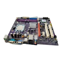
Table of Motherboard Components
Label Component
1394AJ1/1394AJ2* IEEE 1394A header
AGP1 Accelerated Graphics Port
ATX1 Standard 20-pin ATX power connector
AUDIO1 Front audio connector
BAT1 Three volt realtime clock battery
CASFAN1 Case fan connector
CD1 Primary CD-in connector
CNR1 Communications Networking Riser slot
CPU SOCKET Socket A for AMD Athlon/Duron CPUs
CPUFAN1 Cooling fan for CPU
DIM1 ~ DIM2 Two 184-pin DDR SDRAM
FDD1 Floppy disk drive connector
IDE 1 Primary IDE channel
IDE 2 Secondary IDE channel
IR1 Infrared port
J1* System Management Interrupt
JP1 Clear CMOS jumper
JP4* Serial IRQ header
JP5 CPU Frequency jumper
LED1
1
Memory module LED
LSJ1* Single color LED header (for OEM customers only)
PANEL1 Connector for case front panel switches and LED indicators
PCI1 ~ PCI3 Three 32-bit add-on card slots
SJ1 Single color LED header
SPEAKER1 Speaker connector
SPDIF1 SPDIF out header
USB3 Connector for front panel USB ports
USBCR1* USB Card Reader header
VIDEO1* Video In header
*Optional component
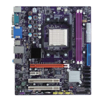
This concludes Chapter 1. The next chapter explains how to install the moth-
erboard.
6
1
The red indicator LED1 turns on if your system is still powered, at which
time memory modules cannot be installed or uninstalled.