5
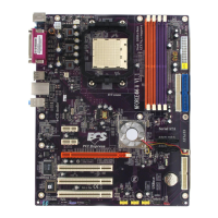
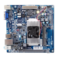
Introducing the Motherboard
Table of Motherboard Components
5 IDE2 Secondary IDE connector
9 SPK1 Speaker header
10 FDD1 Floppy disk drive connector
15 SPDIFO1 SPDIF out header
4 ATX1 Standard 24-pin ATX power connector
LABEL COMPONENT
6 IDE1 Primary IDE connector
8 SYS_FAN1 System cooling fan connector
21 PCIE2~3 PCI Express x1 slots
12 PANEL1 Front Panel switch/LED header
18 BIOS_WP BIOS protect jumper
2 CPU_FAN1 CPU cooling fan connector
22 CAS_FAN1 Case cooling fan connector
3 DIMMA1/2~B1/2 240-pin DDR2 SDRAM slots
17 AUDIO1 Front panel audio header
14 IR1 Infrared header
This concludes Chapter 1. The next chapter explains how to install the motherboard.
11 CLR_COMS Clear CMOS jumper
13 USB3~5 Front Panel USB headers
1 CPU Socket
7 SATA1~4 Serial ATA connectors
16 CDIN1 Analog Audio Input connector
19 PCI1~3 32-bit add-on card slots
20 PCIE1 PCI Express x16 graphics card slot
23 PWR1 4-pin +12V power connector
Socket AM2 for AMD Sempron/Athlon
64/
Athlon 64 X2 Dual-Core/Athlon 64 FX pro-
cessors